Table of Contents
Advertisement
Quick Links
INTRODUCTION:
CONGRATULATIONS on your choice of a Remote Keyless Entry System by Crimestopper Security Products
Inc.
This booklet contains the information necessary for installing, and operating your system.
questions arise, contact your installation dealer or Crimestopper Security Products Inc. at the Tech Support
number below.
*IMPORTANT INFORMATION: Primary and Optional Features
-PRIMARY FEATURES: These are features that must be connected in order for the system to operate
properly i.e. Power & Ground, along with the Primary features of Power Locks & Flashing Lights.
-OPTIONAL FEATURES: Optional features are connected only if desired or agreed upon by the installing
dealer i.e. Horn Chirp and Trunk Pop. These features may require additional parts and labor charges. Consult
with your installer and come to an agreement about your optional features before installation. NOTE: The LED
is required for programmable options.
TECH SUPPORT
Mon-Fri 8:00 AM-4:30 PM Pacific Time
(800) 998-6880
www.crimestopper.com
email@crimestopper.com
REV. 01.2009
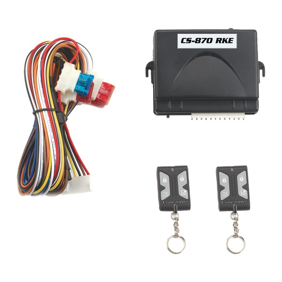
CS-870RKE
REMOTE KEYLESS ENTRY SYSTEM
INSTALLATION & OPERATING INSTRUCTIONS
This device complies with FCC Rules part 15. Operation is subject to the
following two conditions: 1) This device may not cause interference, and (2)
this device must accept any interference that may be received, including
interference that may cause undesired operation. The manufacturer is not
responsible for any radio or TV interference caused by unauthorized
modification to this equipment. Such modification could void the user's
authority to operate the equipment.
If any
Advertisement
Table of Contents

Subscribe to Our Youtube Channel
Related Manuals for CrimeStopper CS-870RKE


Summary of Contents for CrimeStopper CS-870RKE
- Page 1 CONGRATULATIONS on your choice of a Remote Keyless Entry System by Crimestopper Security Products Inc. This booklet contains the information necessary for installing, and operating your system. questions arise, contact your installation dealer or Crimestopper Security Products Inc. at the Tech Support number below. *IMPORTANT INFORMATION: Primary and Optional Features -PRIMARY FEATURES: These are features that must be connected in order for the system to operate properly i.e.
-
Page 2: Table Of Contents
TABLE OF CONTENTS Pre-Installation & Component Mounting……………………..…………………………………………………2-3 Wiring……..……………………………………………………………………………………………………..…….3-4 Power Door Lock Wiring……………………………………………………….………..……………….…...……4-5 Negative Trigger Door Locks………………………….……………………...…...………………………………6 Positive Trigger Door Locks………..………………………….…………………………….…………...……….7 5-Wire Reverse Polarity Trigger Door Locks ………………………….…………………………….…………..8 After Market Door Locks…………….……………………………...9 1-Wire Door Locks……..……………………………………...………………………………………….……….10-12 Wiring Diagram………………………………………………………………………………………………..………13 Transmitter Programming………………………………………………………………………………..…………14 Operating Instructions………………………..…………………………………………………………..………...15 PRE-INSTALLATION CONSIDERATIONS BEFORE BEGINNING, check all vehicle manufacturer cautions and warnings regarding electrical service (AIR BAGS, ABS BRAKES, ENGINE / BODY COMPUTER AND BATTERY). -
Page 3: Wiring
COMPONENT MOUNTING CONTROL MODULE: Locate the module underdash as high as possible. Driver’s Side usually provides an easy location for the majority of the wiring connections. The antenna wire should be routed away from any metal if possible. DO NOT alter the length of the antenna wire, or ground the antenna wire. PROGRAM BUTTON: Mount the button in a hidden but accessible location. -
Page 4: Power Door Lock Wiring
WHITE WIRE: +12Volt PARKING LIGHT (On-Board Relay 10A) A) For Domestic Cars Signal Circuit: Cut 2 Diodes from White wire. Connect fused White wire to switched +12V parking light wire at back of light switch. If this is not possible, connect directly to one of the parking lights at the front of the vehicle. -
Page 5: Power Door Lock Wiring
POWER DOOR LOCK WIRING Negative Trigger (-): Many Imports; Late model Ford & General Motors Negative trigger door lock systems send a Negative (Ground) pulse to existing factory relays to lock and unlock the vehicle doors. Positive Trigger (+): Many General Motors; Chrysler / Dodge / Plymouth Positive trigger door lock systems send a Positive (12V) pulse to existing factory relays to lock and unlock the vehicle doors. -
Page 6: Negative Trigger Door Locks
NEGATIVE TRIGGER DOOR LOCK WIRING Lock Outputs White/Black (N.C.) Green Violet/Black Unlock Outputs Brown (N.C.) Blue Violet Ground Ground Factory Door Lock Module... -
Page 7: Positive Trigger Door Locks
POSITIVE TRIGGER DOOR LOCK WIRING Lock Outputs White/Black (N.C.) Green Violet/Black Unlock Outputs Brown (N.C.) Blue Violet 12 Volts 12 Volts Factory Door Lock Module... - Page 8 5 WIRE REVERSE POLARITY DOOR LOCK WIRING Lock Outputs Lock Outputs White/Black Green Violet/Black Unlock Outputs Brown Blue Violet 12 Volts...
-
Page 9: After Market Door Locks
AFTER MARKET DOOR LOCK WIRING Lock Outputs White/Black Green Violet/Black Unlock Outputs Brown Blue Violet Ground 12 Volts... -
Page 10: Wire Door Locks
1-WIRE RESISTOR DOOR LOCKS Single Wire (Dual Voltage): Late model Chrysler/Dodge/Plymouth Vehicles, some 2000-UP GM Cars Dual Voltage systems have lock/unlock switches that send varying levels of Positive voltage OR Negative ground current to the SAME wire for both lock and unlock. When the vehicle’s Body Computer Module (BCM) or door lock module senses different voltages on this wire, the system will either lock or unlock. - Page 11 Chrysler Town & Country 1996-2000 with alarm Chrysler Town & Country 2001-06 without alarm Chrysler Town & Country 2001-06 with alarm Chrysler Voyager 2001-2006 Dodge Caravan 1996-2000 without alarm Dodge Caravan 1996-2000 with alarm Dodge Caravan 2001-06 without alarm Dodge Caravan 2001-06 with alarm Dodge Charger Dodge Durango 2000 Dodge Durango 2001-02 without alarm...
- Page 12 1-WIRE RESISTOR DOOR LOCKS Lock Outputs White/Black (N.C.) Green Violet/Black Unlock Outputs Brown (N.C.) Blue Violet Ground ¼ Watt Resistor Factory Door Lock Module...
-
Page 13: System Wiring Diagram
Jumper for Door Locks OFF = 0.75 Seconds ON = 3 seconds PROGRAM SWITCH STATUS 15 AMP FUSE 12 Volt Battery (+) Parking Lights Aux 1 Trunk Pop Relay SYSTEM WIRING DIAGRAM Antenna Wire CS-870 RKE 10 AMP FUSE White Gray Ignition Yellow... -
Page 14: Transmitter Programming
1. Turn Ignition ON. 2. Press the Program/Override Button 4 times. After a few second delay, the unit will chirp and flash the lights 4 times. 3. Press button 1 on the remote control you wish to learn. You will get 2 Horn chirps and light flashes indicating the unit is waiting for a 2 the unit will chirp and flash the lights 3 times indicating its waiting for the 3 codes are learned, the unit will automatically exit code-learning mode, otherwise turn key off to exit... -
Page 15: Operation
REMOTE LOCK To lock the doors, press the Lock Symbol (Button #1) on the transmitter. Lights will flash once and LED will begin flashing. You will also hear a single horn chirp (if optional horn chirp feature is installed). REMOTE UNLOCK To unlock the doors, press the Unlock Symbol (Button #2) on the transmitter. - Page 16 ONLINE TECHNICAL SUPPORT Phone (800) 998-6880 www.crimestopper.com/techweb03.html FAX (805) 581-9500 © 2009 Crimestopper Security Products...
Need help?
Do you have a question about the CS-870RKE and is the answer not in the manual?
Questions and answers