
Related Manuals for SunSynk HV Series


Summary of Contents for SunSynk HV Series
- Page 1 HIGH VOLTAGE SERIES LI-ION RACK MOUNT SYSTEM INSTALLER MANUAL HIGH VOLTAGE BATTERY www.sunsynk.com sales@sunsynk.com customerservices@sunsynk.com PLEASE RETAIN FOR v.18 (10/18/23) FUTURE REFERENCE...
-
Page 2: Table Of Contents
Table of Contents IMPORTANT INFORMATION Relay status Version information Scope Fault Pages HV-Series Set Under Voltage (UV) Meaning of Symbols Over Voltage (OV) Symbols on Equipment Under Temperature (UT) General Safety Information Over Temperature (OT) Disclaimer Over Current (OC) Proper Use Different Voltage (DV) Quality Certificate Different Temperature (DT) -
Page 3: Important Information
Please observe the applicable local laws, regulations, and standards. Standards and legal provisions of other countries may be inconsistent with the provisions and specifications. In this manual. In this case, please con- tact our after-sales service personnel, Tel: +852 2884 4318 Fax: +8522884 4816/ Email: www.sunsynk.com / sales@sunsynk.com... - Page 4 Symbol Description Attention! The risk of explosion. Incorrect operation or fire may cause the lithium-ion battery unit to ignite or explode, lead- ing to serious injury. Do not install or operate the battery module in explosive or high-humidity areas. ƒ Store the battery module in a dry place within the temperature range specified in the ƒ...
-
Page 5: General Safety Information
If there are any questions, please contact Sunsynk support after service. Disclaimer Sunsynk Ltd shall not be liable for personal injury, property loss, product damage and subsequent losses under the following circumstances. Failure to comply with the provisions of this manual. -
Page 6: Quality Certificate
Knowledge of handling lithium-ion batteries (transportation, storage, disposal, hazard source). ƒ Understanding and complying with this document and other applicable documents. ƒ Installation video of High Voltage Series Battery can be found at www.sunsynk.com or contact us via ƒ email: support@sunsynk.com SAFETY... -
Page 7: Transport To The End Customers
WARNING Improper use of the battery energy storage system can lead to death. The use of the battery en- ƒ ergy storage system beyond its intended use is not allowed, because it may cause great danger. Improper handling of the battery energy storage system can cause life-threatening risks, serious ƒ... - Page 8 WARNING During transportation, the battery storage rack may be damaged when it is installed with the bat- ƒ tery module. The battery storage rack is not designed to be transported with the installed battery modules. Always transport the battery module and the battery rack separately. Once the battery module is installed, do not move the battery rack, and do not lift it by a lifting device.
-
Page 9: Package Storage Positions
Package Storage Positions Battery Module The battery module can only be transported in an upright position. Please note that the battery rack may be very top-heavy. PREPARATION Tools Required Tool Fix the upper and lower tripods to the side beam and the cross ƒ... -
Page 10: Auxiliary Tools And Materials
Auxiliary Tools and Materials AID/Material Auxiliary Tools/Materials 1. Assemble the battery racks and fix them on the wall or con- nect the two racks. Fastening materials (M4*12 M6*12 screws, M6*100 expansion screws, M6 nuts) 2. Assemble the battery modules and high-voltage control box- es, and fix them to the racks. -
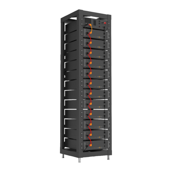
Page 11: Description Of Rack
Description of Rack Type A: 102x2 103x2 104x1 105x1 101x2 106x4 107x3 108x95 109x1 Description Side Upper Cross beam Lower cross beam Lower diagonal beam Upper diagonal beam Base L-bracket M6*12 outer hexagon cross combination screw Hex key High Voltage Series | Installer Manual... - Page 12 Type B: Description Side beam Cross beam Big tripod Small tripod L-bracket assembly Diagonal brace Bottom plate parts Base Rack fastener M4*12 outer hexagon cross combination screw M6*12 outer hexagon cross combination screw M6*100 expansion screw High Voltage Series | Installer Manual...
-
Page 13: Installation Of Rack
Installation of Rack Type A: 1. Connect the upper cross beams (102) and lower cross beams (103) with the two rack sides (102) using M6*12 external hexagonal cross combination screws (108) and a PHILIP2 # screwdriver. 201x1 1. Use a PHILIP2 # screwdriver and M6*12 external hex combination screws (108) to attach the L-bracket (107) assembly horizontally to the side joist. - Page 14 Type B: 1. Take out two side beams and upper and lower crossbeams to form a rectangular frame, connect with side beams and crossbeams using big tripods and small tripods, and then fix big and small triangular supports with side beams and crossbeams using M6*12 outer hexagon cross combination screws and a PHILIP2 # screwdriver.
- Page 15 HV Battery Rack Manual High Voltage Series | Installer Manual...
-
Page 16: Description Of Battery Module
Description of Battery Module Name Description Battery module negative pole (black) Connection position of battery module communication and BCOM OUT power supply output Battery module positive pole (orange) Connection position of battery module communication and BCOM IN power supply input Description of High-Voltage Control Box Name Description... -
Page 17: Description Of Battery Module In Rack
Name Description Position Grounding wire Connection to the battery rack and the ground point Front identification Connection position with next HVB-100A750V communica- OUT COM Rear tion input Connection position with previous HVB-100A750V commu- IN COM Rear nication input Communication interface with charging and discharging PCS COM Rear equipment... - Page 18 Description Type Connected to external PCS positive power cord (EPCable5.0) Optional Connected to external PCS negative power cord (ENCable5.0) Optional Connected to external 12V power cord (EPWRCable5.0) Optional Connected to external device communication cable (ECOM Cable5.0) Optional The following table presents the definition for PCS, IN, and OUT connection pins. All use the same pin num- ber sequence shown in the next image: Pin No.
-
Page 19: Battery Module Installation On Rack
Battery Module Installation on Rack DANGER Insufficient or no grounding may cause an electric shock. Device malfunctions, and insufficient or no grounding may cause device damage and life-threatening electric shocks. PLEASE NOTE Before installing the battery, please turn the manual switch of the high-voltage control box to the off position. -
Page 20: External 12V Power Supply Of High-Voltage Control Box
To operate the high-voltage control box with an external 12V power supply, please contact our service per- sonnel. Hotline: +852 2884 4318, Email: support@sunsynk.com. In the factory configuration, the high-voltage control box is supplied with working voltage from an internal power supply unit. -
Page 21: Fault Indication
Fault Indication When the corresponding fault type occurs, the red background indicator on the screen will light up. The description of each is shown below. Over Voltage Under Voltage Over Temperature Under Temperature Insulation failure, there is a risk of current leakage Over Current Other Faults Different Voltage... -
Page 22: Main Screen
Main Screen This screen shows the main information of the system, like the Voltage (V), SOC (%), Current (A), Total Energy (MWh), the BMU number, and the protocol ID. Click this screen to enter the system maintenance menu. Click on each Fault Indication to enter in the Fault Page. System Maintenance Menu The Menu page presents information about High Voltage Series Battery system, voltage, temperature, ver- sion, and the relay status. -
Page 23: Volt/Temp Information
Volt/Temp information This screen shows the information about the system voltage and temperature. Relay status This screen shows statuses related to the relay. In addition, in this page you can clear the relay adhesion. Version information This page contains all the information about BMS, BMU, and Screen software and hardware versions. High Voltage Series | Installer Manual... -
Page 24: Fault Pages
Fault Pages In "Home Screen" page, click on each Fault Indication to enter in the Fault Page related. Under Voltage (UV) This screen shows the faults related to the under voltage of the system. Over Voltage (OV) This screen shows the faults related to the over voltage of the system.. High Voltage Series | Installer Manual... -
Page 25: Under Temperature (Ut)
Under Temperature (UT) This screen shows the faults related to the under temperature of the system. Over Temperature (OT) This screen shows the faults related to the over temperature of the system. Over Current (OC) This screen shows the faults related to the over current of the system. High Voltage Series | Installer Manual... -
Page 26: Different Voltage (Dv)
Different Voltage (DV) This screen shows the faults related to the different voltage of the system. Different Temperature (DT) This screen shows the faults related to the different temperature of the system. Other Faults (OF) This screen shows the other faults of the system. High Voltage Series | Installer Manual... -
Page 27: Maintenance Interface
Maintenance Interface For safety, please unplug the power cord of the positive and negative interfaces before maintenance. PLEASE NOTE When inserting the SD card, unplug the battery power cord and manually turn the air switch to the off position. HVESS-MONITOR USE INSTRUCTIONS Main Page PROTECTION 2023... -
Page 28: Function List
Function List Communica- Function Function Name Function Description tion Category Category "INTER-CAN BUS" or "PCS CAN BUS" can be Communica- Communication selected tion configu- configuration of Click the relevant button to start or stop the ration CAN BUS communication with BMS. 1. -
Page 29: Function Description
Function Description CAN Communication Configuration 1. Insert the network cable into IN port, click the OPEN INTER-CAN BUS button to start the INTER-CAN com- munication, and click the button again to stop such communication. 2. Insert the network cable into the PCS port, click the OPEN PCS CAN BUS button to start the INVERTER CAN communication, and click the button again to stop such communication. - Page 30 In the parallel system application, click the OPEN INTER-CAN BUS button. By default, the data monitoring interface will display the real-time information of the module group number 01. To display other module information, switch to the desired module group number. After the communication is available, the specific cell number and temperature information will be displayed in real-time.
-
Page 31: Parallel Information
Parallel Information In the parallel info display interface, the real-time information of racks that are parallel to each other is dis- played successively according to the serial number. PROTECTION 2023 Group Life: 161 More Info. ALARM 00:10 SysStatus Life Parallel PowerOn Voltage(v) SOC(%) Current(A) Positive Precharge Discharge Charge Heater Pos Heater Neg BMU MaxChgCur(A) MaxDs GENERAL... -
Page 32: History Records
History Records Select Records and click the READ ALL button. The HVESS-Monitor starts the task of reading history records and creates the reading process with the slave computer. After receiving the response, the received history records will be analysed and displayed in the Flash record list. The latest history records are displayed below the list. -
Page 33: History Events
History Events Select Events, and click the READ ALL button. The HVESS-Monitor will start the task of reading history events, and create the reading process with the slave computer. After receiving the response, the received history events will be analysed and displayed in the list, and the latest time will be displayed above the list. Click the SAVE button to save the read history events to the user-selected path for offline analysis. -
Page 34: Hvess-Monitor Real-Time Data Storage
HVESS-Monitor Real-Time Data Storage Click the RECORDING button to start the real-time saving of operational data, and click the STOP button to stop the real-time saving. Click the SAVE button to save the recorded real-time operational data to the us- er-selected path for offline analysis. -
Page 35: Parameter
Parameter The parameter interface includes BMS parameters and BMU parameters. The operation method is the same. Click the READ ALL button to display such data as ALARM, ALM Recover, ALM Delay, PROTECTION, PROT Recover and PROT Delay on corresponding windows, these are factory default values. When the reading is complete, the corresponding windows will become blue. -
Page 36: Inter-Can Firmware Upgrade
INTER-CAN Firmware Upgrade Make a selection in the red box of the BMS CAN-BUS upgrade and BMU CAN-BUS upgrade interface. Click the Browser button, select the configuration file to be upgraded from the computer, or drag the BIN file to be upgraded to the upgrade interface. -
Page 37: Manufacture
Manufacture Click the Read button to read the product serial number and other related information. The default opera- tional or working mode is Factory Mode. To display more details, change to Debug Mode and click the Set button. The number of read/set successes/failures is displayed in the lower right corner. Restart to automati- cally return to Factory Mode. -
Page 38: Cell Types
Cell Types High Voltage Series | Installer Manual... -
Page 39: Inverter Information
Inverter Information When the INVERTER CAN communication is connected externally, click OPEN PCS CAN BUS. This interface will display the information related to the communication with the inverter. PROTECTION 2023 Group Life: 161 More Info. ALARM 00:10 Summary GENERAL PCS Time Parallel Base Info Charge Voltage(V) -
Page 40: Pcs Can Firmware Upgrade
PCS CAN Firmware Upgrade Click the Browser button, select the configuration file you need to upgrade from the computer, or drag and drop the BIN file you need to upgrade to the upgrade interface. The HVESS-Monitor will read and analyse the data in the file and display it on the corresponding input interface. -
Page 41: Fault Description
FAULT DESCRIPTION Different types of faults are below: Fault Types Trigger Conditions Charge over-current alarm Exceeding the parameter set value and set time (More than 105A, 2s; more than 125A, 5s; more than Charge over-current protection 140A, 2s; lower than 5°C, set value*0.5) Discharge over-current alarm Discharge over-current protection Charge overtemperature alarm... - Page 42 Fault Types Trigger Conditions BMS connector overtemperature alarm Exceeding the parameter set value and set time BMS connector overtemperature protection Exceeding the parameter set value and set time BMU connector overtemperature alarm Exceeding the parameter set value and set time BMU connector overtemperature protection Exceeding the parameter set value and set time Power loop overtemperature alarm...
-
Page 43: Fault Types Summary In Screen And Hvess-Monitor
FAULT TYPES SUMMARY IN SCREEN AND HVESS-MONITOR Abbreviation Screen Protection Event HVESS-Monitor Protection HVESS-Monitor Alarm Description Event Description Event Description BMS southward connector BMU connector overtemper- BMU connector overtem- overtemperature ature protection perature alarm BMS northward connector BMS connector overtemper- BMS connector overtem- overtemperature ature protection... - Page 44 Abbreviation Screen Protection Event HVESS-Monitor Protection HVESS-Monitor Alarm Description Event Description Event Description Abnormal number of BMU Abnormal number of BMU BMU lost BMU lost RTC clock fault RTC clock fault Current module fault Current module fault SCHG total voltage acquisition SCHG total voltage acquisi- fault tion fault...
-
Page 45: Maintenance And Upgrade
MAINTENANCE AND UPGRADE CAUTION Improper decommissioning may cause damage to the equipment and/or battery inverter. ƒ Before maintenance, ensure that High Voltage Series Battery is decommissioned according to ƒ relevant provisions. PLEASE NOTE All maintenance work shall comply with local applicable regulations and standards. The USB disk port of High Voltage Series Battery has the functions of upgrading firmware and recording battery data, which can be used as an auxiliary tool. -
Page 46: Usb's Upgrade Step
USB's Upgrade Step 1. USB type: USB2.0, FAT32; 2. Create the upgrade folder according to the directory; 3. Place the upgrade file provided by the supplier in the upgrade folder; 4. Turn on the battery, and insert the USB flash disk after the blue indicator is on; 5. -
Page 47: Disposal
2. Waste batteries may contain pollutants that can damage the environment or your health if im- properly stored or handled. 3. Batteries also contain iron, lithium and other important raw materials, which can be recycled. For more information, please visit www.sunsynk.com. Do not dispose of batteries as household waste! High Voltage Series | Installer Manual... -
Page 48: Appendix
APPENDIX Circuit Diagram for On Grid System with 12V Supply High Voltage Series | Installer Manual... - Page 49 HK Address: Room 702-704, 7/F Texwood Plaza, 6 How Ming Street, Kwun Tong, Kowloon, Hong Kong. UK Address: Sunsynk, 17 Turnstone Business Park, Mulberry Avenue, Widnes, Cheshire, WA8 0WN. SA Address: Globaltech Sunsynk South Africa (Pty) Ltd, Unit 2 Highview Boulevard, Ferndale 2194.
Need help?
Do you have a question about the HV Series and is the answer not in the manual?
Questions and answers