Subscribe to Our Youtube Channel
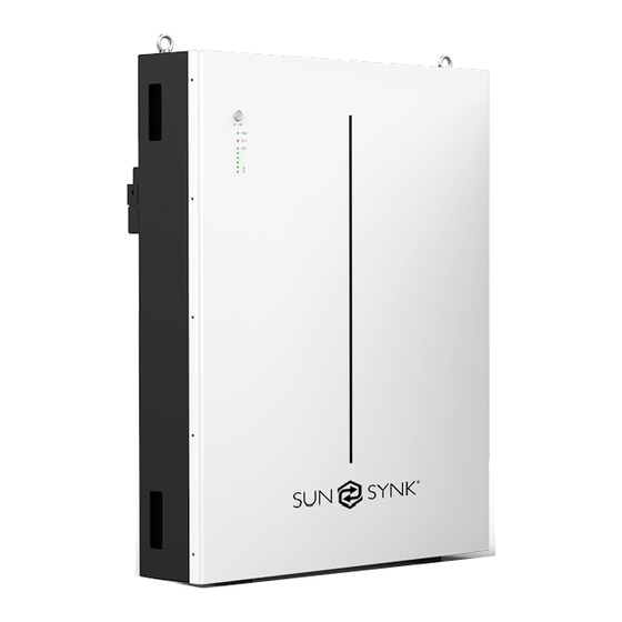
Summary of Contents for SunSynk SUN-BATT-15.97
- Page 1 SUN-BATT-15.97 Product Description Sunsynk UK Ltd. Address: 7 Abbey Square, Chester CH1 2HU, England. Tell: +852-2884 4318 Fax: +852-2884 4816...
-
Page 2: Table Of Contents
CONTENTS 1 Technical Data 2 Product Overview Brief Introduction Interface Introduction 2.2.1 Switch ON/OFF 2.2.2 LED Indicator Definition 2.2.3 CAN / RS485 Port 2.2.4 RS232 Port 3 Installation Guide Checking Before Installation 3.1.1 Checking Outer Packing Materials 3.1.2 Checking Deliverables Tools Installation requirements 3.3.1... -
Page 3: Technical Data
1. Test conditions: 100% depth of discharge (DoD), 0.2C rate charge & discharge at 25℃ 2. Charge/discharge derating occurs when the operating temperature from -10℃ to 5 ℃.& 45 ℃ to 55 ℃. 3. Condition apply. Refer to SUN-BATT-15.97 Warranty Letter... -
Page 4: Product Overview
(more than 3 seconds) ON/OFF button of MASTER battery, LED will flash, battery system will automatically encode and assign ID to each slave battery, then battery system will Multiple SUN-BATT-15.97 can be connected in parallel to expand capacity and power, 8 operate normally. -
Page 5: Led Indicator Definition
. Battery Level Indicator For single SUN-BATT-15.97, switch OFF rocker switch (near positive/negative connector). Light For multiple SUN-BATT-15.97 in parallel, switch OFF rocker switch of all slave batteries Light Light first.Then switch OFF rocker switch of MASTER battery. -
Page 6: Installation Guide
Wall bracket Hanging Pearl wool bracket Carton Battery Supporting structure INSTALLATION Pearl wool GUIDE Pictures Quantity Description Installation flow chart 1PCS Battery Check Before Prepare Determine The Start Installation Installation Tools Installation Position Wall bracket 1PCS Hanging bracket Electrical Install Wall 2PCS Install Battery Connection... -
Page 7: Tools
3.2 Tools 3.4 Installation Instructions 3.4.1 Dimensions Model Tools Knife Measuring tape Socket wrench (10/16mm) Installation Rubber mallet Cross Screwdriver Hammer drill(12mm) ESD gloves Safety goggles Anti-dust respirator Protection Safety shoes 720mm 160mm Minimum mounting distance between battery pack and equipment: 150mm 150mm 150mm... -
Page 8: Installation Procedure
STEP 3 3.4.2 Installation Procedure Use a crane to lift the ring on the battery pack and attach it to the STEP 1 wall bracket. Drill the hole with an 12mm drill bit as follows and fix the wall bracket to the wall. Lift the battery pack by crane M10*80 M10*80... - Page 9 STEP 7 When multiple batteries are connected in parallel, follow the following wiring mode. Parallel Cables length 1000mm;Power Cables length 1500mm. scheme one to PCS CAN port CAN RS232 RS232 CAN RS232 Parallel Parallel communication cable communication cable Lin In Link Out Lin In Link Lin In Link MASTER...
-
Page 10: Maintenance
MAINTENANCE 4.1 Recharge Requirements During Normal Storage Recharge Requirements When Over Discharged Battery should be stored in an environment with temperature range between -10°C ~ Over discharged (90% DoD) battery should be recharged according to following table, +45°C, and maintained regularly according to following table with 0.5C (150A) current till 40 otherwise over discharged battery will be damaged.


Need help?
Do you have a question about the SUN-BATT-15.97 and is the answer not in the manual?
Questions and answers