Table of Contents
Advertisement
Quick Links
Advertisement
Table of Contents

Related Manuals for COX CRUISER ZTR


Summary of Contents for COX CRUISER ZTR
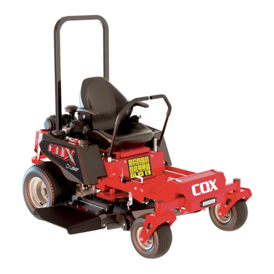
- Page 1 CRUISER ZTR RIDE-ON MOWER OWNER/OPERATOR’S MANUAL INCL ILLUSTRATED PARTS LIST MODEL:A22723K PRODUCT CODES: CZ24C42 - CZ26C48 - CZ26C52 READ THIS MANUAL BEFORE OPERATING MACHINE DEATH, PERSONAL INJURY AND/OR PROPERTY DAMAGE MAY OCCUR UNLESS INSTRUCTIONS IN THIS MANUAL ARE FOLLOWED A22723K JAN 2024...
- Page 2 This will not only help in extending the lifespan of your machine but also ensure its optimal performance and efficiency. Like all mechanical equipment, your COX lawn mower requires regular cleaning and maintenance. It is crucial to adhere to the lubrication guidelines specified in this manual to maintain its condition.
-
Page 3: Table Of Contents
Contents OWNERS INFORMATION ....................MAINTENANCE SCHEDULE .................... SPECIFICATIONS ......................- 1 - SAFETY SYMBOLS ................... - 2 - SAFETY DECALS ....................- 2 - SAFETY INFORMATION ..................- 5 - 3.1. Training ....................- 5 - 3.2. Preparation ....................- 5 - 3.3. - Page 4 6.7. Deck Cleaning ..................- 20 - 6.8. Blade Inspection ..................- 20 - 6.9. Replace Blade ..................- 21 - AJUSTMENT ....................- 21 - 7.1. Cutting Height Adjustment ................ - 21 - 7.2. Deck Leveling Adjustment................. - 22 - 7.3.
- Page 5 Cox Industries (Australia) Pty Ltd Email: sales@coxmowers.com.au 1041 Beaudesert Road Archerfield QLD 4108...
-
Page 6: Owners Information
Located on The Front Frame ENGINE NO.: _________________________ (As applicable) Located on Engine refer Engine Owner Manual DATE OF PURCHASE: __________________________________ OWNERS NAME: ADDRESS: TOWN/CITY: STATE: AUTHORISED COX DEALER/DISTRIBUTOR: ADDRESS: TOWN/CITY: STATE: PRE DELIVERY CHECK LIST Check parts Assemble Service Instruction ❑... -
Page 7: Maintenance Schedule
We are proud that you have purchased a Cox ZTR and urge you to follow these instructions to obtain the maximum life for your machine. If in doubt check with your Dealer. MAINTENANCE SCHEDULE BEFORE EACH USE Check engine oil level, adjust if required Check tyre pressures, adjust if required Check engine air cleaner foam pre-cleaner, service if required. - Page 8 12 MONTHS OR 100 HOURS which ever occurs first Change engine oil filter Check for loose fasteners, tighten if required Change engine oil Check operation of safety switches, service if required Check engine spark plug, clean, adjust, or replace if required Check tyre pressures, adjust if required If fitted clean engine exhaust spark arrester Check mowing attachment cutter blades, bolts, nuts, housing and...
- Page 9 27 MONTHS OR 225 HOURS which ever occurs first Change engine oil if operating under heavy load or high ambient temperature Check tyre pressures, adjust if required Check engine air cleaner foam pre-cleaner, service if required * Check mowing attachment cutter blades, bolts, nuts, housing and Check engine rotating screen/finger guard, clean if required * guards for wear or damage, replace if required Check operation of safety switches and replace if required...
-
Page 10: Specifications
SPECIFICATIONS Product Code CZ24C42 CZ26C48 CZ26C52 Engine Engine Type COX POWER COXPOWER Model No. VP680S VP750S Horsepower (G.I.H.P.) 14.5kw 18kw Displacement 679cc. 750cc No-load r.p.m. 3600rpm 3600rpm Charging System 12VDC 12.5 amp. negative ground Starter Electric Electrical System Safety interlocked... -
Page 11: Safety Symbols
1. SAFETY SYMBOLS 2. SAFETY DECALS All DANGER, WARNING, CAUTION and ⚫ instructional messages on your machine must be read and followed carefully. Personal injury occur these instructions disregarded. This information is crucial for your safety! This SAFETY ALERT SYMBOL is used both in this manual and on the machine to alert Keep all safety decals legible. - Page 12 94.6069410 On The CHUTE 94.6069750 94.6069760 Behind The Rear Wheel, LH & RH 94.6069450 Besides The Belt Shields, LH & RH 94.6069927 Console 94.6069922 94.6069923 On The Front Fender, LH & RH 94.6069430 Rear Shield, LH&RH 94.6069730 On The Front Of Deck,42'' 94.6069700 On the mower deck,42'' - 3 -...
- Page 13 94.6069890 Front Of Deck,48'' 94.6060985 On the mower deck,48''&52'' 94.6069560 Front Of Deck,52'' 94.6069420 Besides The Belt Shields, LH&RH 94.6069680 On The Tank 94.6051016 Besides The Left Tank 94.6051017 Besides The Right Tank 94.6051018 94.6051019 On The Front Frame On The Front Fender - 4 -...
-
Page 14: Safety Information
unqualified individuals to operate the equipment. Keep young children and pets away from ⚫ the zone of operation to avoid accidents or hazards to other people or their property. 3.2. Preparation While mowing, always wear tight belted ⚫ clothing. Wear protected footwear. Never 94.6061001 operate the machine in bare feet, open On The Console... -
Page 15: Operational Safety
gasoline can burn you and others and deck installed. The proper stability of the can damage property. machine depends on the weight of the Fill the fuel tank outdoors, in an open mower deck. ⚫ area, when the engine is cold. Wipe up Keep bystanders away from equipment ⚫... -
Page 16: Maintenance Safety
Disengage PTO, stop engine, select park support. Always use adequate wheel ⚫ brake, remove key, and wait for all chocks on tyres remaining on the ground. movement to stop before dismounting, If running the engine in an enclosed ⚫ adjusting, cleaning, or unclogging the area, use an exhaust pipe extension to machine. -
Page 17: Assembly Instructions
Sand areas where paint is chipped and ⚫ repaired to prevent rust. Lubricate all locations to prevent moisture damage during storage. 4. ASSEMBLY INSTRUCTIONS 4.1. Install Seat Locate and align the seat with the seat pan (Refer to Figure 4), torque all the nuts until the seat is snug. -
Page 18: Service Engine
corresponding voltage of your battery The battery charger used should have and the recommended charging time. an output of 16 volts and 7 amps or Charge the battery until it reaches a full less. Using a charger with higher charge of 12.6 volts or greater. output can cause damage... - Page 19 The Throttle Control (C) is the large black The two Steering Levers control speed, ⚫ lever located beside the console to the motion, and direction of the machine and right of the seat. The throttle is used to are located on each side of the seat. The left control engine speed.
-
Page 20: Pre-Start Check List
conditions. These circuits should be checked to transmission and loss of control of the machine. before each operation to ensure they are Check for oil and fuel leaks. working properly. See Table 2 for check list ⚫ on these circuits. IMPORTANT The Start Circuits will keep engine from When mowing in dusty conditions,... -
Page 21: Mounting And Dismounting The Mower
⚫ Test safety interlock systems (Refer to operation of the machine immediately. ⚫ Table 2). Perform these tests in a clear Consult your COX dealer for assistance open area and keep bystanders away. and further instructions. Table 2 Left Right... -
Page 22: Cold Weather Starting Tips
control or damage to the machine. DO NOT allow children to approach the machine while the engine is running. CAUTION DO NOT operate the machine around Help prevent personal injury. Learn use open flames. of the steering levers and practice at DO NOT operate the engine when an half throttle... - Page 23 To stop motion, move both steering levers back to neutral. The machine is equipped with springs to automatically return both levers to neutral. If levers DO NOT automatically return to neutral, see your authorized COX dealer for adjustment. IMPORTANT become confused during...
- Page 24 Figure 9 - 15 -...
-
Page 25: Mowing
grass should be mowed at a low speed, 5.7. Mowing while thin medium height grass can be cut at a faster ground speed. Always operate WARNING engine at full governed RPM when mowing. Inspect the area before mowing, This is necessary to maintain proper blade picking up all rocks, twigs and other speed to produce a clean cut. -
Page 26: Stopping The Engine
the bottom and try to back the mower up when operating the machine with the slope slowly. If you cannot back up ROPS. At other times, wearing the the slope or if you feel uneasy on it, DO seatbelt is at the operator’s discretion. NOT operate on it. -
Page 27: Loading Machine
down and outward from machine. or more, add a fuel stabilizer to the fuel system. Fuel stabilizer is an acceptable 5.11. Loading Machine additive in minimizing the formation of fuel gum deposits during storage. Add WARNING stabilizer to fuel in fuel tank or storage Loading a machine onto a trailer or container. -
Page 28: Lubrication
surface. 6.1.2 Check when engine cold. 6.1.3 Clean area around dipstick. Remove the lipstick and wipe oil off. Reinsert the dipstick according engine manufacturer’s recommendations. Remove the dipstick and read the oil level. 6.1.4 If the oil level is low, wipe off the area around the oil fill cap, remove cap and fill to the “FULL”... -
Page 29: Battery Maintenance
maintenance ensure the battery is securely CAUTION fastened in place, especially if it has been DO NOT use high-pressure water or removed. steam to clean the engine or drive compartment. Water and cleaning 6.7. Deck Cleaning detergent damage electrical IMPORTANT components and terminals, possibly After each use remove grass buildup leading to component and safety... -
Page 30: Replace Blade
broken or bent blades, damaged or material and block securely when worn bolts and nuts or damaged cutter removing blades. Careless disc, otherwise damage and premature improper handling may result in wear will result from vibration. Replace serious injury. blades, bolts and nuts only in pairs to Inspect blades before... -
Page 31: Deck Leveling Adjustment
nut (B) on the mower each deck hanger (Refer to Fig.18). Figure 16 7.2. Deck Leveling Adjustment. 7.2.1 Position mower on a flat surface. Figure 18 7.2.2 Stop engine, wait for all moving parts 7.2.8 Slightly loosen the nut (B) on the to stop, and remove key. -
Page 32: Dump Drive Belt Adjustment
blocks. DO NOT rely solely on mechanical or hydraulic jacks or lifts for support. Make sure two drive wheels keep away from the ground. Figure 19 7.3.3 Increase belt tension by turning the draw nut (C) clockwise and decrease belt tension turning draw... -
Page 33: Seat Adjustment
1/2"(12mm) for you by your local authorised Cox Dealer. when it is in the free state. Use the same method to adjust the brake adjustable lever. - Page 34 Problem Possible Cause Corrective Action 1.PTO is engaged. 1.Disengage the PTO. 2.Parking brake is not 2.Set the parking brake. engaged. 3.Ensure the drive levers are in the neutral lock 3.Drive levers are not in position. neutral lock position. 4.Charge the battery. See Check Battery Charge 4.Battery does not have a full and Recommended Jump-Starting Procedure charge.
- Page 35 Clutch will clutch. connections and replace if necessary. not engage. 3.Damaged coil. 4.Inadequate current supply. 2 To 5. Contact your local COX Dealer. Clutch will 5.Rotor/armature air gap is too not engage. large. - 26 -...
- Page 36 - 27 -...
-
Page 37: Illustrated Parts List (Ipl)
9. ILLUSTRATED PARTS LIST (IPL) 9.1. MOWER ASSEMBLY - 28 -... -
Page 38: Chassis Assembly
9.2. CHASSIS ASSEMBLY - 29 -... - Page 39 Item Part No. Description Qty. Others 94.4012951-ZH1P6006 Front Crossbeam 94.4012958 Spacer Sleeve 94.4012957 Spacer Gasket 94.7011123 Hex Bolt M10×80 94.7031602 Washer Φ16 94.7011620 Hex Bolt M16×80 94.7084311 Copper Bushing 94.7032006 Washer Φ20 94.7011634 Sholder Bolt M20x60 94.7021004A Lock Nut 94.7031009 Washer Φ10 94.7021603...
-
Page 40: Hydrostatic Transaxle/Wheel Assembly
Item Part No. Description Others 94.7010820 Hex Flange Bolt M8×20 94.5040940 Isolator 94.4060069 Anti Slip Tape 94.7030402 Washer Φ4 94.7020403A Lock Nut 94.4060066-ZH1P6006 Fuel Line Protector 94.7080470 Washer 9.3. HYDROSTATIC TRANSAXLE/WHEEL ASSEMBLY - 31 -... - Page 41 Item Part No. Description Qty. Others 94.ZJ-GPEE-SKDB-2PLX Hydrostatic Transaxle, RH ZT3100 Hex Bolt M10×55 94.7011040 Washer 94.7031009 Φ10 Drive Connecting Rod 94.4039495-ZH1P6006 94.7041002 Lock Washer Φ10 Washer 94.7030819 Φ8 Hex Bolt M8×60 94.7010807 Hydrostatic Transaxle, LH 94.ZJ-KPEE-SKDC-3PLX ZT3100 Hex Bolt M8×70 94.7010880 94.6090326-ZH1P6006...
-
Page 42: Steering Assembly
9.4. STEERING ASSEMBLY Item Part No. Description Oty. Others 94.7051511 Return Pull Spring 94.7010893 Hex Bolt M8×30 94.6090325 Spring Hanging Plate 94.7020819 Hex Lock Nut 94.7020803A Hex Lock Nut Joint Bearing RH/Rod 94.4066760 94.7030819 Washer Φ8 94.7181630 Hex Nut 94.4133431 Bearing Pedestal 94.4269810 Handle Motion Pivot/LH... - Page 43 Item Part No. Description Oty. Others 94.7010880 Hex Bolt M8×70 94.7060014 Bearing 6002-2RS 94.7131806 D Pin 94.2020450 Damper 94.7020804 Hex Nut 94.7010826 Hex Bolt M8×45 94.4130008-ZH1P6006 Left Mounting Plate 94.2401354 Park Switch 94.5013320 Handle Grip- Foam 94.2132050 End Cap 94.4010008 Steering Handle RH 94.4300002 Control Arm /RH...
-
Page 44: Deck Carrier Assembly
9.5. DECK CARRIER ASSEMBLY - 35 -... - Page 45 Item Part No. Description Oty. Others 94.4058191-ZH1P6006 Lift Lever 94.7011151 Hex Bolt M10×100 94.4310210 Lift Bearing Block 94.4151750 Lift Bearing Lower Plate 94.4058201-ZH1P6006 Cutter Deck Hanger 94.4058202 Deck Hanger Shaft 94.7010820 Hex Bolt M8×20 94.7131806 D-Pin B10×32×3.2× 94.7131008 Deck Mount Pin 27.5 94.7291260 Joint Bolt...
-
Page 46: Seat Assembly
9.6. SEAT ASSEMBLY - 37 -... - Page 47 Item Part No. Description Oty. Others 94.4060413-ZH1P6006 Front Plate 94.7240999 Socket Button Screw M8×16 94.7020803A Hex Lock Nut 94.7030819 Washer Φ8 94.7020820 Type B Leaf Spring Nut 94.7180812 Square Neck Bolt M8×20 94.7010837 Hex Bolt M8×35 94.7030413 Pop Rivet Φ4.8×12 94.1014340 Connecting Shaft 94.7131806...
-
Page 48: Fuel Tank Assembly
9.7. FUEL TANK ASSEMBLY - 39 -... - Page 49 Item Part No. Description Oty. Others 94.2082260 Fuel Tank LHS 94.2081031 EPA Fuel Cap 94.2114608 Fuel Tank Liner 94.CJT075 Dumping Valve 94.2114605 Breather Hose 94.7083440 Fuel Tank Gromet 94.2133770 Elbow Fitting 94.2114601 1/4"Fuel Line Hose 94.9120001 Left Fuel Line Braiding 94.7150170 Hose Clamp-Spring 94.2128030...
-
Page 50: Pedal Assembly
9.8. PEDAL ASSEMBLY Item No. Part No. Description Oty. Others 94.4012941-CC067636B3JN Foot Panel 94.7020803A Hex Nut 94.7083590 Spacer 94.7030819 Washer Φ8 94.7010807 Hex Bolt M8×60 - 41 -... -
Page 51: Rear Shidld Assembly
9.9. REAR SHIELD ASSEMBLY Item Part No. Description Oty. Others 94.4060061-ZH1P6006 Shield/Rear 94.4060062-ZH1P6006 Left Rear Shield 94.4060063-ZH1P6006 Right Rear Shield 94.7010894 Hex Flange Bolt M8×16 94.7030819 Washer Φ8 94.7020803A Hex Lock Nut 94.7010876 Hex Bolt M8×55 94.4060064-ZH1P6006 Muffler Guard - 42 -... -
Page 52: Engine Assembly
9.10. ENGINE ASSEMBLY - 43 -... - Page 53 Item Part No. Description Oty. Others 94.1TJZQC684 ENGINE 94.7020803A Hex Lock Nut 94.7030819 Washer Φ8 94.4221320-ZH1P6006 Clutch Stop 94.7180818 Hex Bolt M8×25 94.1040021 A126 Pulley 94.7110608A 6.35×6.35×30 94.4124390 Small Spacer 94.7083470 Large Spacer 94.7101430 Electromagnetic PTO Clutch 94.4124400 Clutch Sleeve 94.4071060 Clutch Plate 94.7010075A...
- Page 54 - 45 -...
- Page 55 Item Part No. Description Oty. Others 94.1TJZQC755 ENGINE 94.7020803A Hex Lock Nut 94.7030819 Washer Φ8 94.4221320-ZH1P6006 Clutch Stop 94.7180818 Hex Bolt M8×25 94.1040021 A126 Pulley 94.7110608A 6.35×6.35×30 94.4124390 Small Spacer 94.7083470 Large Spacer 94.7101430 Electromagnetic PTO Clutch 94.4124400 Clutch Sleeve 94.4071060 Clutch Plate 94.7010075A...
- Page 56 - 47 -...
- Page 57 Item Part No. Description Oty. Others 94.1TJZQC753 ENGINE 94.7020803A Hex Lock Nut 94.7030819 Washer Φ8 94.4221320-ZH1P6006 Clutch stop 94.7180818 Hex Bolt M8×25 94.1040021 A126 Pulley 94.7110608A 6.35×6.35×30 94.4124390 Small Spacer 94.7083470 Large Spacer Electromagnetic PTO 94.7101440 Clutch 94.9054890 Transfer Harness 94.4124420 Clutch Sleeve 94.4071060...
- Page 58 - 49 -...
- Page 59 Item Part No. Description Oty. Others 94.1TJZQC755 ENGINE 94.7020803A Hex Lock Nut 94.7030819 Washer Φ8 94.4221320-ZH1P6006 Clutch stop 94.7180818 Hex Bolt M8×25 94.1040021 A126 Pulley 94.7110608A 6.35×6.35×30 94.4124390 Small Spacer 94.7083470 Large Spacer Electromagnetic PTO 94.7101440 Clutch 94.9054890 PTO Loom 94.4124420 Clutch Sleeve 94.4071060...
- Page 60 9.11. 42” MOWING ATTACHMENT - 51 -...
- Page 61 Item Part No. Description Qty. Others 94.4241715-ZH4P6064 42”Mower Deck 94.7011080 Hex Bolt M10×110 94.7031009 Washer Φ10 94.4240585 Spacer 94.8011800 Anti-scalp Roller 94.4262150-03 Spacer 94.7021004A Hex Lock Nut Blade Spindle Assembly 94.7021039 Hex Lock Nut 94.4241738-ZH4P6064 Blade Deck 94.4241739 Blade 94.4161000 Saddle Washer 94.4241740 Hex Bolt...
- Page 62 Item Part No. Description Qty. Others 94.7042003 Lock Washer Φ20 94.7022004 Hex Nut M20×1.5 94.7021607 Hex Nut 94.7021603 Hex Lock Nut 94.7031613 Large Washer Φ16 94.7031602 Washer Φ16 94.4241750-ZH4P6064 Belt Guard RH 94.7059750 Idler Pulley Spring 94.7181005 Hook Bolt M10×70 94.7021018 Nyloc Nut 94.4241744-ZH4P6064...
- Page 63 9.12. 48” & 52” MOWING ATTACHMENT Item Othe Part No. Description Qty. 94.4241725-ZH4P6064 48”Mower Deck 48” 94.4241735-ZH4P6064 52”Mower Deck 52” 94.4241730-ZH4P6064 Belt Guard RH - 54 -...
- Page 64 Item Othe Part No. Description Qty. 94.7020820 Leaf Springs Nut 94.7291260 Hook bolt M12×60 94.7021242 Hexagon Flange Nuts 94.4241740 Swing Blade Bolt 94.4241749 Blade 137 94.4161000 Saddle Shaped Washer 94.4241732-ZH4P6064 Swing Blade Installation Plate 48” 94.4241751-ZH4P6064 Swing Blade Installation Plate 52”...
- Page 65 Item Part No. Description Qty. Others 94.7031602 Washer Φ16 94.4241729-ZH4P6064 Dynamic Tensioning Arm 94.4240022 Spacer 94.7060401 Deep Groove Ball Bearing 6204-2RZ-HRB 94.7021204A Hex Lock Nut 94.7021201 Hex Nut 94.7031221 Washer Φ12 94.4241745-ZH4P6064 Dust Cover 94.1041690 Fixed Pulley 94.4241747-ZH4P6064 Deck Right Limit Plate 94.1042105 Spindle Pulley for 48"/52”...
-
Page 66: Electrical Assembly
9.13. ELECTRICAL ASSEMBLY - 57 -... - Page 67 Item Part No. Description Oty. Others 94.5041160 Battery Cushion 12V Battery locally 94.4181281 Battery Hold Down Strap Rod 94.4152270-ZH1P6006 Battery Hold Down Plate 94.7020606 Wing Nut 94.6631006 Hour Meter 94.6631007 USB Charger 94.6637300 Conduit 94.2117431 LED Light Switch 94.E72919-1 Ignition Switch 94.9010548 PTO Clutch Switch 94.7020505A...
-
Page 68: Rops Assembly
9.14. ROPS ASSEMBLY (Optional) - 59 -... - Page 69 Item Part No. Description Oty. Others 94.7021004A Hex Lock Nut 94.7031009 Washer Φ10 94.4260843-ZH1P6006 Lower Anti Roll Frame 94.5013230 Star Shaped Handle 94.7031221 Washer Φ12 94.7011251 Hex Bolt M12×70 94.7133221 Locking Pin Shaft 94.4162520-ZH1P6006 U-shaped Spring 94.4260842-ZH1P6006 Upper Anti Roll Frame 94.7133130 R Pin Φ4.5×80...
-
Page 70: Decals Assembly
94.6069680 Fuel Tank 53×38 94.6069450 Warning 7 101.6×82.5 94.6069410 Warning 3 108×63.5 94.6069420 Warning 4 82.5×21.5 94.6051016 COX Fuel Tank LH 264×110 94.6051017 COX Fuel Tank RH 264×110 94.6051018 COX Front 486×134 94.6069700 42” Belt 90×70 42” 94.6069730 42" Cutting Deck 95×57.5... - Page 71 NOTES - 62 -...
- Page 72 Web Site Address https://coxmowers.com.au Email: sales@coxmowers.com.au - 63 -...
Need help?
Do you have a question about the CRUISER ZTR and is the answer not in the manual?
Questions and answers