Table of Contents
Advertisement
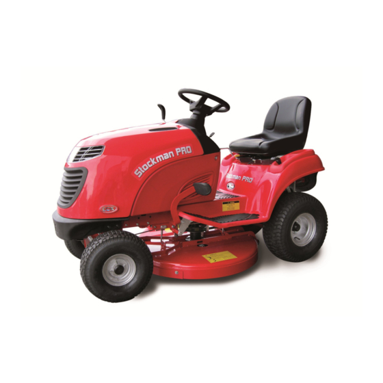
Model A12612A
21HP B&S 32" Cut & 40" Cut Side Discharge
OWNER/OPERATORS MANUAL
READ THIS MANUAL BEFORE OPERATING MACHINE
DEATH, PERSONAL INJURY AND/OR PROPERTY DAMAGE MAY OCCUR UNLESS
INSTRUCTIONS IN THIS MANUAL ARE FOLLOWED
NOTE: Bring this Manual when Service & or Warranty work is required.
Rev 3 18/07/2014
Page 1
Advertisement
Table of Contents

Related Manuals for COX A12612A Stockman PRO


Summary of Contents for COX A12612A Stockman PRO
- Page 1 Model A12612A 21HP B&S 32” Cut & 40” Cut Side Discharge OWNER/OPERATORS MANUAL READ THIS MANUAL BEFORE OPERATING MACHINE DEATH, PERSONAL INJURY AND/OR PROPERTY DAMAGE MAY OCCUR UNLESS INSTRUCTIONS IN THIS MANUAL ARE FOLLOWED NOTE: Bring this Manual when Service & or Warranty work is required. Rev 3 18/07/2014 Model Number A12612A Page 1...
-
Page 2: Owners Information
ENGINE ( Located on Engine) B&S MODEL NO:______________TYPE____________ CODE_______________ DATE OF PURCHASE:__________________________________ ISSUED TO: OWNERS NAME: ADDRESS: STATE: TOWN/CITY: ISSUED BY: AUTHORISED COX DEALER/ DISTRIBUTOR: ADDRESS: TOWN/CITY: STATE: PRE DELIVERY CHECK LIST Check parts Assemble Service Instruction ... -
Page 3: Safety Instructions
SAFETY INSTRUCTIONS Read, understand, & follow all instructions in the Owner/ Never mow while barefoot or wearing open sandals or Operators manual. thongs. Wear long trousers and heavy shoes. Know the controls and how to stop the engine quickly in ... -
Page 4: Unpacking Instructions
PRE-DELIVERY INSTRUCTIONS UNPACKING INSTRUCTIONS ! Caution you can be seriously injured by sharp nails protruding from the shipping Inspect the shipping crate and contents for damage. crate. Position the shipping crate on a firm flat level surface with at least 2.1 meters distance from any Remove the plastic sheet covering the tractor. - Page 5 SERVICE CLUTCH PLATE Start engine and run for approximately 1 minute at about half throttle, switch engine off to allow clutch arm to centre BATTERY itself then (If unused for 3 months or more) loosen the four square head set screws on the clutch a) Remove R.H Side cover and rear console cover, then plates using tube spanner (AM006C1) and tommy bar remove battery retaining bracket.
- Page 6 Figure 1 Headlight Switch Ignition Switch Drive Pedal Start Foot Switch Cutting Height Adjustment Lever Mowing Attachment Engagement Lever Throttle Control Lever Park Brake Lever Engine Air Inlet Vents Seat Adjustment Lever Foot Brake Pedal Rev 3 18/07/2014 Model Number A12612A Page 6 Page 6...
-
Page 7: Operating Instructions
OPERATING INSTRUCTIONS towards you and up, stop at and depress foot switch to start The controls and their desired cutting height and push engine with ignition key. functions are as lever into adjacent notch. To follows; lower cutting height, pull Fuel tap knob- towards you and lower the lever Used to shut off fuel line when... - Page 8 cranking for more than 15 heavy loads are being towed neutral position or vice versa if seconds can damage the starter or carried. Excessive pressure traveling in reverse. Should motor. Short starting cycles should not need to be applied failure of the drive system occur give best starter motor life.
-
Page 9: Maintenance Schedule
MAINTENANCE SCHEDULE BEFORE EACH USE Check engine oil level, adjust if required Lubricate as per required Check engine air cleaner foam pre-cleaner, service if req Check tyre pressures, adjust if required Check engine rotating screen/finger guard, clean if req Grease stub axles Check engine air inlet console screen, clean if required Check mowing attachment cutter blades, bolts, nuts, disc/s, Check operation of safety switches, service if required... - Page 10 9 MONTHS OR 75 HOURS WHICH EVER OCCURS FIRST Change engine oil if operating under heavy load or high ambient Check tyre pressures, adjust if required temperature Grease stub axles * Check engine air cleaner foam pre-cleaner, service if required * Check for loose fasteners, tighten if required Check engine rotating screen/finger guard, clean if required * Check battery condition, service if required...
- Page 11 21 MONTHS OR 175 HOURS WHICH EVER OCCURS FIRST Change engine oil if operating under heavy load or high ambient Check tyre pressures, adjust if required. temperature. Grease stub axles *. Check engine air cleaner foam pre-cleaner, service if required *. Check battery condition, service if required.
-
Page 12: Maintenance Instructions
Wipe vents with hand, rag or brush to essential that the maintenance schedule specified in this booklet. remove debris from vent openings. supplied be performed by your COX a. Mowing in damp or wet conditions. INDUSTRIES Dealer. This will ensure the b. Mowing in rough or dusty... - Page 13 We are proud that you have purchased a Cox product and urge you to follow these instructions to obtain the maximum life for your machine. If in doubt check with your supplier. Rev 3 18/07/2014...
- Page 14 BODY COMPONENTS & TOOL KIT TOOL KIT ITEM PART NUMBER DESCRIPTION AM006C1 Spanner, Tube, Clutch Plate AM007 Bar, Tommy AM295 Spanner, Tube, Spark Plug 13126 Gauge, Clutch Clearance 13127 Hook, Spring Pull TOOL KIT 90134 Key, Ignition Switch Rev 3 18/07/2014 Model Number A12612A Page 14...
-
Page 15: Table Of Contents
BODY COMPONENTS & TOOL KIT ITEM PART NUMBER DESCRIPTION A126233 Battery Cover A126234 Left Side Cover A126235 Right Side Cover 90045 Right Foot Mat 90046 Left Foot Mat A126247 Hand Brake Shroud A126248 Height Adjustment Shroud 90072 Centre Foot Mat 90075 Mud Flap 90076... - Page 16 BONNET COMPONENTS (18.5HP & 21HP ONLY) BONNET COMPONENTS Rev 3 18/07/2014 Model Number A12612A Page 16...
- Page 17 BONNET COMPONENTS ITEM PART NUMBER DESCRIPTION 15132 Globe A126221R Hinge, Bonnet New Era 90038 Head Light Reflector 90039 Head Light Lens A126240 Air Duct Intake A126241 Grille A126242 Left Bonnet Vent A126243 Right Bonnet Vent 90130 Buffer, Rubber 9003108G Bonnet incl Mountings and Spacers A126044 Mounting, Side, Bonnet A126045...
- Page 18 SEAT COMPONENTS Rev 3 18/07/2014 Model Number A12612A Page 18...
-
Page 19: Screw
SEAT COMPONENTS PART NUMBER DESCRIPTION 13060 Spring, Seat 14128 Cap, Seat Spring A126050 Seat A126052 Kit,Adjust,Seat,4" Travel Adjuster Runner BHSSC0512 Replacement Screw 13247 Replacement Washer A126442Z Bracket, Hinge, Left A126444Z Bracket, Hinge, Right A126449R Base, Seat BHSSC0512 Screw, Button N05CN SP1PNCSM Switch, Plunger W05M202... - Page 20 ENGINE & CONTROL COMPONENTS Rev 3 18/07/2014 Model Number A12612A Page 20...
-
Page 21: Grommet
ENGINE & CONTROL COMPONENTS ITEM PART NUMBER DESCRIPTION 13206 Valve, Drain, Oil 14107 Fuel Hose 90068 Fuel Tank AM293 Petrol Tap AM294 Grommet CF01 Cap, Fuel A126266 Throttle Control Handle 90078 Control, Throttle 13367 Exhaust Pipe 13368 Exhaust Bracket Exhaust Gasket B&S Engine Screw CHSS0512C... - Page 22 Rev 3 18/07/2014 Model Number A12612A Page 22...
-
Page 23: Wiring Diagram
WIRING DIAGRAM ITEM PART NUMBER DESCRIPTION Battery, Automotive,12V,CMFU1,9PL,240CCA SH0620M Screw, Battery NHM6 Nut, Battery 90129 Switch, Ignition 90134 Key, Ign Switch Engine SP2PNONCSM Switch, Plunger, Disengagement 90128 Switch, Light SP1PNCSM Switch, Plunger, Seat AM159 Solenoid, SH0616M Bolt, Solenoid NM6NT Nut, Solenoid 15132 Globe AM211... -
Page 24: Brake Components
BRAKE COMPONENTS Rev 3 18/07/2014 Model Number A12612A Page 24... - Page 25 BRAKE COMPONENTS ITEM PART NUMBER DESCRIPTION A126262 Park Brake Handle 90264 Pivot, Brake Pedal 90219 Brace, Pivot, Brake Pedal 9007706D Pad, Pedal, Brake A126420R Lever, Brake Pedal 90222 Link, Pull, Brake Rod AM230 Bush - Plastic B0620C Bolt NF06CN 90221 Rod, Brake 90024 Lever, Park Brake...
-
Page 26: Steering Components
STEERING COMPONENTS Rev 3 18/07/2014 Model Number A12612A Page 26... - Page 27 STEERING COMPONENTS ITEM PART NUMBER DESCRIPTION 13012 Bush, Flanged, Nylon AM25399J Disc, Universal Joint A126008Z Shaft, Steering, Lower A126018Z Pivot, Idler, Left A126020Z Pivot, Idler, Right A126024Z Pivot, Crank A126030 Chain, Roller A126022Z Crank, Steering AM017C1 Steering Shaft Bush With Collar A126016Z Idler, Chain, Steering A126026Z...
- Page 28 FRONT AXLE COMPONENTS Rev 3 18/07/2014 Model Number A12612A Page 28...
-
Page 29: Model Number A12612A
FRONT AXLE COMPONENTS ITEM PART NUMBER DESCRIPTION 13107 Washer 13242 Pin, Pivot, Front Axle 13009 AM021 Sleeve, Spacer, Bearing BB204212N Bearing, Ball STU600X6 Tube TT600X698A Tyre & Tube 13016 13203 Stub Axle Left Hand 13204 Stub Axle Right Hand A142103R Axle Beam, Front A126204R Link, Drag, Mowing Attachment... - Page 30 REAR AXLE COMPONENTS Rev 3 18/07/2014 Model Number A12612A Page 30...
- Page 31 REAR AXLE COMPONENTS ITEM PART NUMBER DESCRIPTION A142362Z Arm, Chain Tensioner PIFBB126598A Idler, Flat W051218 Washer SH0820M Screw WS050216 Washer, Lock, Spring W061216 Washer WW0616 Washer, Wave NF06CN AM024 Flangette BB25SAN Bearing, Ball Screw, Set, Hex Soc, M 6x0.75x7 AM025 Lock Collar GS0808M Screw, Set...
- Page 32 MODEL CA130: DIFFERENIAL COMPONENTS Rev 3 18/07/2014 Model Number A12612A Page 32...
- Page 33 MODEL CA130: DIFFERENIAL COMPONENTS (OPTIONAL) ITEM PART NO DESCRIPTION AM07099C Hub Cap CP3-225 Split Pin AM340 Wheel Adaptor Sleeve CHSBM8X75 Retaining Bolt NS08F WSM8X2X2 Spring Washer AM324 Washer BB15329N Bearing AM313 Bronze Bush AM366 Adaptor Wheel NM6NT W06MN Washer AM3203L Case, Plain Half AM323 Gasket...
-
Page 34: Transmission Components
TRANSMISSION COMPONENTS Rev 3 18/07/2014 Model Number A12612A Page 34... - Page 35 TRANSMISSION COMPONENTS ITEM PART NUMBER DESCRIPTION 90013 Clutch Rod 90069 Clutch Pedal 9014806B Crank, Link, Drive 90261 Pivot, Drive Pedal A126463R Lever, Drive Pedal BB25SAN Bearing, Ball AM364 Sleeve, Spacer, Shaft N10FT SKIT65 Intershaft Sprocket & Key AM363 Shaft, Mounting, Clutch Plate SK03 90276 Bolt, Pivot, Arm, Clutch...
- Page 36 CLUTCH ARM COMPONENTS FROM CR16.5-32 S/N 4831 CR21.0-32 S/N 9413 CR21.0-40 S/N 5056 Rev 3 18/07/2014 Model Number A12612A Page 36...
- Page 37 CLUTCH ARM COMPONENTS FROM CR16.5-32 S/N 4831 CR21.0-32 S/N 9413 CR21.0-40 S/N 5056 ITEM PART NUMBER DESCRIPTION A100025 A132013B Arm, Clutch BB255220D Bearing, Ball A126514 Shaft, Clutch, PTO, Non-Self Locking BB255215NN Bearing, Ball A126515 Pulley, PTO, CI A126516 Pulley, Mount, Cone, CI A126518 Washer A126519Z...
- Page 38 CUTTER CONTROL COMPONENTS Rev 3 18/07/2014 Model Number A12612A Page 38...
- Page 39 CUTTER CONTROL COMPONENTS ITEM PART NUMBER DESCRIPTION A126260 Disengagement Handle A126261 Cutter Height Handle 13015 90229 Bush, Link, Adjust 9023006J Mechanism, Link, Suspension, Mower AM185B0 Cutter Lifting Link AM369 Bush - Plastic NF06CN 90231 Link, Adjust, Disengage 90232 Link, Bushed, Disengage 90233 Bush, Pivot, Disengage 90234...
- Page 40 32” MOWING ATTACHMENT COMPONENTS Rev 3 18/07/2014 Model Number A12612A Page 40...
- Page 41 32” MOWING ATTACHMENT COMPONENTS ITEM PART NUMBER DESCRIPTION A100003 Spring, Torsion, Deflector KIT226 Kit, Deck, Cutter, 805(32") DEC116 Decal, Danger, Mowing Attachment NF06CN BCHSNM8X20 Bolt, Cup, Sq Neck W061216 Washer NM8NT AM036D9 Roller Plastic 92102 Pin, Roller AM274 Fastener, Push-on 251301 Rod, Adj, Cutter Brake AM034H0...
- Page 42 A15312A 40” MOWING ATTACHMENT MAIN COMPONENTS Rev 3 18/07/2014 Model Number A12612A Page 42...
- Page 43 A15312A 40” MOWING ATTACHMENT MAIN COMPONENTS ITEM PART NUMBER DESCRIPTION NM10NT A152043Z Axle, Tensioner B1090M Bolt A152253R Guard, Pulley, Left A152255R Guard, Pulley, Right NCM6X1.6X9.5 Nut, Cage 98004 Bracket, Guide, Belt NM8NT SH0825M Screw A152272 Arm, Brake, Cutter 10.1 AM033I95 Pad, Brake, Cutter 10.2 PR0205...
- Page 44 A15312A 40” MOWING ATTACHMENT ANCILLARY COMPONENTS Rev 3 18/07/2014 Model Number A12612A Page 44...
- Page 45 A15312A 40” MOWING ATTACHMENT ANCILLARY COMPONENTS ITEM PART NUMBER DESCRIPTION A152005B Housing, Bearing, Flange BB205215NS Bearing, Ball SH1030M Screw NM10NT Nut, A118003 Pulley, Cutter, Ci A100025 WSM10X3.7X2.5 Washer, Lock Spring SH1030M Bolt 9800311M Axle, Flanged 9801611M Flange 98009 Sleeve, Spacer, Bearing BB255215NN Bearing, Ball 98010...
- Page 46 Rev 3 18/07/2014 Model Number A12612A Page 46...
- Page 47 NOTES:- —————————————————————————— —————————————————————————— —————————————————————————— —————————————————————————— —————————————————————————— —————————————————————————— —————————————————————————— —————————————————————————— ————————————-—————————————— —————————————————————————— —————————————————————————— —————————————————————————— —————————————————————————— —————————————————————————— ———————————————————-——————— —————————————————————————— —————————————————————————— —————————————————————————— —————————————————————————— —————————————————————————— ——————————————————————————- —————————————————————————— —————————————————————————— —————————————————————————— —————————————————————————— —————————————————————————— ——————————————–——————————–— —————————————————————————— —————————————————————————— ——————————————————————————- Rev 3 18/07/2014 Model Number A12612A Page 47...
- Page 48 70 Landseer Street Acacia Ridge Qld 4110 Australia PH 07 3323 2222 FAX 07 3344 6233 Web Site Address: www.coxmowers.com.au Email: sales@coxmowers.com.au Rev 3 18/07/2014 Model Number A12612A Page 48...
Need help?
Do you have a question about the A12612A Stockman PRO and is the answer not in the manual?
Questions and answers