Table of Contents
Advertisement
Advertisement
Table of Contents

Related Manuals for Optek TF16


Summary of Contents for Optek TF16
- Page 1 Instruction Manual optek-sensors TF16 optek-Manual--1004-2006-02--TF16-US-2011-06-20 PN: 1004-2006-02 (-52) optek-Danulat GmbH Emscherbruchallee 2 45356 Essen Germany Phone: +49-(0)201-63409-0 Fax: +49-(0)201-63409-999 E-Mail: info@optek.de Internet: www.optek.com...
- Page 2 This instruction manual is written to assist the user in proper procedures for trouble-free operation. It is explicitly pointed out that optek-Danulat GmbH assumes no responsibility for loss or damage caused due to improper use of this instruction manual or products described herein.
-
Page 3: Table Of Contents
Technical data and exploded views ..................7 Exploded view of TF16 / TF16-N sensor................11 Exploded view of TF16-HT / TF16-HT-N sensor ..............12 Exploded view of TF16-PV / TF16-PV-N sensor ..............13 Exploded view of TF16-HT-PV / TF16-HT-PV-N sensor ............ 14 Installation .......................... - Page 4 Gaskets (not wetted) ....................29 9.5.4 Screw sets ....................... 29 9.5.5 Small part sets ......................30 9.5.6 Installation material ....................30 9.5.7 Accessories cable sets .................... 30 Declaration of conformity ..................... 31 Contacts ..........................32 - II - optek-Manual--1004-2006-02--TF16-US-2011-06-20 www.optek.com...
-
Page 5: Using The Instruction Manual
Using the instruction manual Using the instruction manual Validity of the instruction manual This instruction manual is valid for TF16, TF16-N sensors and their variants. There are the following variants: • HT • PV • HT-PV Abbreviations mean the following sensor options: •... -
Page 6: Pictograms And Signal Words
If the possible cause of risk can be specified, the corresponding pictogram pre- cedes instructions: Danger! Electrical voltage. This pictogram indicates danger due to electrical voltage. Caution! This pictogram indicates information on how to avoid material damage. Note! This pictogram indicates instructional or general advice. - 2 - optek-Manual--1004-2006-02--TF16-US-2011-06-20 www.optek.com... -
Page 7: Returns And Disposal
For disposal, disassemble the system components and separate them according to different material groups. Dispose of materials according to national and local regulations. If no agreement has been made, products may be shipped to optek for disposal. - 3 - optek-Manual--1004-2006-02--TF16-US-2011-06-20... -
Page 8: Intended Use
Intended use Intended use The optek-sensors TF16 and their variants are to be applied only as scattered light turbidimeters for liquids and gases in inline applications according to the technical data. The use of the sensors in hazardous locations is prohibited. -
Page 9: Description Of Tf16 / Tf16-N Sensors
Description of TF16 / TF16-N sensors Description of TF16 / TF16-N sensors The TF16 model is a high precision dual channel scattered light turbidimeter. It measures direct light and light scatterd from particles in the process medium at an angle of 11°. The sensor is made entirely of stainless steel and designed for direct installation into pipelines. - Page 10 Description of TF16 / TF16-N sensors Due to the small scattering angle, direct light and scattered light practically travel the same distance in the process medium. This is why product specific disturbances such as color or color changes of the carrier medium as well as soilings on windows may be optimally compensated.
-
Page 11: Technical Data And Exploded Views
Technical data and exploded views Technical data and exploded views Tab. 1 Technical data TF16 TF16 TF16-PV TF16-HT TF16-HT-PV Material sensor body made of stainless steel 1.4571, SS 316 Ti (standard) Special materials ® ® 1.4435 (SS 316 L), 1.4539, 1.4462, TFM 4215, Hastelloy... - Page 12 Technical data and exploded views Tab. 2 Technical data TF16-N TF16-N TF16-PV-N TF16-HT-N TF16-HT-PV-N Material sensor body made of stainless steel 1.4571, SS 316 Ti (standard) Special materials ® ® 1.4435 (SS 316 L), 1.4539, 1.4462, TFM 4215, Hastelloy C4, Hastelloy C22, Titanium, ®...
- Page 13 DN 100 (DIN 11851) SS 316 Ti Flange 1.4571 / 0120-1106-03 welded 1" (ASME B16.5 RF, 150 lbs) SS 316 Ti Flange 1.4571 / 0120-1306-03 welded 1.5" (ASME B16.5 RF, 150 lbs) SS 316 Ti - 9 - optek-Manual--1004-2006-02--TF16-US-2011-06-20 www.optek.com...
- Page 14 *) Optical path length (OPL) using standard windows model A is given in column OPL A-A. For the TF16 sensor, the sensor body and window combination have to be chosen so that a type A window is installed on the detector side and the optical path length is 40 mm (1.58 '').
-
Page 15: Exploded View Of Tf16 / Tf16-N Sensor
Technical data and exploded views Exploded view of TF16 / TF16-N sensor 20 22 20 21 Fig. 4 Photo and exploded view of TF16 / TF16-N Tab. 5 Exploded view explanations Explanation Explanation Sensor body Window ring M58 x 1.5, incl. 8 screws M5 Window ring M24 x 1.5, incl. -
Page 16: Exploded View Of Tf16-Ht / Tf16-Ht-N Sensor
O-Ring 10.10 x 1.60, Viton Æ O-Ring 4.00 x 1.00 Viton ® Screw M5 x 6 (DIN 84), 1.4571 (316 Ti) Purge connection M5, Ms/Ni Note! For TF16-HT, the cable set always has to be equipped with plug-protection. - 12 - optek-Manual--1004-2006-02--TF16-US-2011-06-20 www.optek.com... -
Page 17: Exploded View Of Tf16-Pv / Tf16-Pv-N Sensor
Exploded view of TF16-PV / TF16-PV-N sensor 20 22 22 20 21 20 20 21 12 13 Fig. 6 Photo and exploded view of TF16-PV / TF16-PV-N Tab. 7 Exploded view explanations Explanation Explanation Sensor body Window ring M58 x 1.5, incl. 8 screws M5 Window ring M24 x 1.5, incl. -
Page 18: Exploded View Of Tf16-Ht-Pv / Tf16-Ht-Pv-N Sensor
O-Ring 10.10 x 1.60, Viton O-Ring 4.00 x 1.00 Viton Screw M5 x 6 (DIN 84), 1.4571 (316 Ti) Purge connection M5, Ms/Ni Note! For TF16-HT-PV, the cable set always has to be equipped with plug-protection. - 14 - optek-Manual--1004-2006-02--TF16-US-2011-06-20 www.optek.com... -
Page 19: Installation
Installation Installation Standard sensor bodies — installation instructions Installation instructions are provided in the armatures instruction manual. - 15 - optek-Manual--1004-2006-02--TF16-US-2011-06-20 www.optek.com... -
Page 20: Installation Of The Sensor
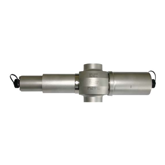
5. Screw on sensor assemblies for detector and lamp sides to the sensor body hand-tight (right-hand thread, fig. 9). It is recommended to use the supplied installation paste. Fig. 9 Installed sensor, example TF16 sensor - 16 - optek-Manual--1004-2006-02--TF16-US-2011-06-20 www.optek.com... -
Page 21: Air Purge
10 minutes at a maximum of 0.5 bar (7.25 psi) gauge pressure. In case you do not have air purge supply of appropriate quality, you can use the optek Air Drying System ADS. 3. Reduce air pressure to approx. 0.1 bar (1.45 psi). -
Page 22: Connection To Converter C4000
Connection of the sensor cable without plug-protection on the detector and lamp side: 1. Loosen the connection cover of the sensor. 2. Plug in the sensor cable. 3. Screw-tighten the protection cover. Fig. 12 Connection of the sensor cable without plug-protection - 18 - optek-Manual--1004-2006-02--TF16-US-2011-06-20 www.optek.com... - Page 23 2. Ensure there is an O-Ring (7, fig. 13) for plug-protection. 3. Plug in the sensor cable. 4. Fasten each of the four screws of the plug-protection (19) with washer. Fig. 13 Connection of the sensor cable with plug-protection - 19 - optek-Manual--1004-2006-02--TF16-US-2011-06-20 www.optek.com...
- Page 24 DETECTOR INPUTS LAMP [F] V DC acc. to cable length OPTEK - DANULAT MADE IN GERMANY Fig. 14 Detector inputs and lamp outputs of the converter C4422 Letters stand for • A - D Detector inputs • E - F...
- Page 25 Cable length max. output C4101 C4121 C4201 C4221 C4202 C4222 C4322 C4422 type 2 sensors TF16 A / C 250 m / 820 ft TF16 B / D 2 sensors AF26 A / C 250 m / 820 ft TF16...
-
Page 26: Faults
Should you have any difficulty clearing the fault, feel free to contact our customer service. To solve the problem efficiently, we ask you to have the sheet with system data of your sensor or system at hand. Please find our contact details in chapter 11, page 32. - 22 - optek-Manual--1004-2006-02--TF16-US-2011-06-20 www.optek.com... - Page 27 Small deviations given in % calibration of the receiving mA-output mA-input. • Send system (converter and sensor) to optek for checking purposes. If necessary, the None of the above mentioned Defect of converter sensor body can remain in errors can be detected.
-
Page 28: Maintenance
Statistical service life amounts to 3 years, for UV lamps to 1–2 years. Note! The used detector is not subjected to measurable aging when used properly. - 24 - optek-Manual--1004-2006-02--TF16-US-2011-06-20 www.optek.com... -
Page 29: Exchange Of The Lamp Module
6. Insert the new lamp module into the sensor. 7. Fasten the four screws. 8. Re-connect the sensor cable. 9. Switch on the converter. 10. Follow the instructions given in chapter 9.4, page 27. Fig. 15 Exchange of the lamp module - 25 - optek-Manual--1004-2006-02--TF16-US-2011-06-20 www.optek.com... -
Page 30: Exchange Of Detector Module
Maintenance Exchange of detector module The detector module may only be exchanged at the factory. Please contact your contact person at optek. - 26 - optek-Manual--1004-2006-02--TF16-US-2011-06-20 www.optek.com... -
Page 31: Return To Operation After The Exchange Of Lamp Module And Detector Module
3. Check the system's zero-point (see instruction manual of the converter). 4. Document your settings using the form (see instruction manual of the con- verter). 5. Check measuring results with regard to plausibility. 6. If settings and measuring results are correct, enable measuring. - 27 - optek-Manual--1004-2006-02--TF16-US-2011-06-20 www.optek.com... -
Page 32: Spare Parts And Accessories
Lamp modules / detector modules / optics modules Tab. 12 Spare parts — lamp module Name / type Old part number New part number lamp module TF16 2100-0202-02 1426-3137-1401-01 Tab. 13 Spare parts — wavelength modules Wavelength module Old part number... -
Page 33: Standard Window
BM 0410-0057-03 type CM 0410-0058-03 ** others on request Observe that for TF16 sensor and its variants only type A windows may be in- stalled on the detector side! 9.5.3 Gaskets (not wetted) Tab. 16 Spare parts — gaskets ®... -
Page 34: Small Part Sets
Accessories — cable sets with SS-plug-protection Cable sets with SS-plug-protection*** New part number 2312-0315-0005-00 10 m 2312-0315-0010-00 20 m 2312-0315-0020-00 30 m 2312-0315-0030-00 40 m 2312-0315-0040-00 50 m 2312-0315-0050-00 *** other cable lengths on request - 30 - optek-Manual--1004-2006-02--TF16-US-2011-06-20 www.optek.com... -
Page 35: Declaration Of Conformity
Fermenter Control (FCXX with X=0..2); Haze Control (HC 4XXX, X=0..5) and one or several sensors of the series AF16, AF26, AF45, AF46, TF16-N, DTF16, ASD19, ASD25, AS16, AS56, ACF60 have been developed, constructed and manufactured in conformity with the mentioned EC directives. -
Page 36: Contacts
Toll free call: +1 800 371 4288 E-Mail: info@optek.de Fax: +1 262 437 3699 E-Mail: info@optek.com Netherlands Singapore optek-Danulat bv optek-Danulat Pte. Ltd. Grote Brugse Grintweg 12a 25 Int’l Business Park 4005 AH Tiel / Netherlands #05-109-f German Centre Phone: +31-344-683800 Singapore 609916 Fax: +31-344-653950...
Need help?
Do you have a question about the TF16 and is the answer not in the manual?
Questions and answers
The panel said ' SIGNAL LOSS C