Table of Contents
Advertisement
Advertisement
Table of Contents

Related Manuals for Optek AF45


Summary of Contents for Optek AF45
- Page 1 Instruction Manual optek-sensors AF45 optek-Manual--1004-2003-02--AF45-US-2011-01-04 PN: 1004-2003-02 (-52) optek-Danulat GmbH Emscherbruchallee 2 45356 Essen Phone: +49-(0)201-63409-0 Fax: +49-(0)201-63409-999 E-Mail: info@optek.de Internet: www.optek.com...
- Page 2 This instruction manual is written to assist the user in proper procedures for trouble-free operation. It is explicitly pointed out that optek-Danulat GmbH assumes no responsibility for loss or damage caused due to improper use of this instruction manual or products described herein.
-
Page 3: Table Of Contents
Intended use ..........................4 Description of the AF45 sensor ....................5 Technical data and exploded views ..................7 Exploded view of AF45 sensor ..................... 9 Exploded view of AF45-HT sensor ..................10 Exploded view of AF45-VB sensor ..................11 Exploded view of AF45-HT-VB sensor ................12 Exploded view of AF45-PV sensor .................. - Page 4 Validation retrofit sets ....................40 9.8.6 Small part sets ......................40 9.8.7 Installation material ....................41 9.8.8 High voltage power supply (HVPS) .................41 9.8.9 Validation filter ......................41 9.8.10 Accessories cable sets ....................42 Declaration of conformity .....................43 Contacts ..........................44 - II - optek-Manual--1004-2003-02--AF45-US-2011-01-04 www.optek.com...
-
Page 5: Using The Instruction Manual
Using the instruction manual Using the instruction manual Validity of the instruction manual This instruction manual is valid for AF45 sensors and their variants. There are the following variants: • HT • VB • PV • HT-VB • HT-PV • HT-VB-PV •... -
Page 6: Pictograms And Signal Words
If the possible cause of risk can be specified, the corresponding pictogram pre- cedes instructions: Danger! Electrical voltage. This pictogram indicates danger due to electrical voltage. Caution! This pictogram indicates information on how to avoid material damage. Note! This pictogram indicates instructional or general advice. - 2 - optek-Manual--1004-2003-02--AF45-US-2011-01-04 www.optek.com... -
Page 7: Returns And Disposal
For disposal, disassemble the system components and separate them according to different material groups. Dispose of materials according to national and local regulations. If no agreement has been made, products may be shipped to optek for disposal. - 3 - optek-Manual--1004-2003-02--AF45-US-2011-01-04... -
Page 8: Intended Use
Intended use Intended use The optek-sensors AF45 and their variants are to be applied only as absorption sensors for liquids and gases in inline applications according to the technical data. The use of the sensors in hazardous locations is prohibited. You can purchase flameproof sensors for hazardous locations from optek. -
Page 9: Description Of The Af45 Sensor
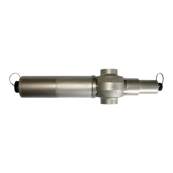
Description of the AF45 sensor Description of the AF45 sensor This sensor is a high precision UV absorption sensor. It measures attenuation of light passing through the process medium. The sensor was designed for direct installation into pipelines. Fig. 1... - Page 10 Description of the AF45 sensor Attenuation of light intensity, as a result of absorption and / or scattering of substances in the process medium, is described by the Lambert-Beer Law. It states, the logarithm of the transmission loss is proportional to concentration of the substance.
-
Page 11: Technical Data And Exploded Views
Technical data and exploded views Technical data and exploded views Tab. 1 Technical data AF45 Material sensor body made of stainless steel 1.4571; SS 316 Ti (standard) ® ® 1.4435 (SS 316 L), 1.4539, 1.4462, TFM 4215, Hastelloy C4, Hastelloy... - Page 12 0.9 kg / 10 m Lamp cable (1.5 mm 1.2 kg / 10 m Lamp cable (2.5 mm 1.5 kg / 10 m Lamp cable (4.0 mm Detector cable (AF45) 1.2 kg / 10 m - 8 - optek-Manual--1004-2003-02--AF45-US-2011-01-04 www.optek.com...
-
Page 13: Exploded View Of Af45 Sensor
® O-Ring 21.95 x 1.78, Viton module (see table 17 on page 38) Screw M4 x 10 DIN 912 A4 Detector module AF45, incl. wavelength module (see table 18 on page 39) Lamp module AF45 ® O-Ring 10.10 x 1.60, Viton... -
Page 14: Exploded View Of Af45-Ht Sensor
Screw M5 x 6 (DIN 84), 1.4571 (316 Ti) Purge connection M5, Ms/Ni Window ring M24 x 1.5, incl. 8 screws M5 Note! For AF45-HT, the cable set always has to be equipped with plug protector. - 10 - optek-Manual--1004-2003-02--AF45-US-2011-01-04 www.optek.com... -
Page 15: Exploded View Of Af45-Vb Sensor
® O-Ring 50.52 x 1.78, Viton O-Ring 21.95 x 1.78, Viton Housing lamp assembly AF45, incl. wavelength Detector module AF45, incl. wavelength module (see module (see table 17 on page 38) table 18 on page 39) ® Screw M4 x 10 DIN 912 A4 O-Ring 10.10 x 1.60, Viton... -
Page 16: Exploded View Of Af45-Ht-Vb Sensor
Window ring M24 x 1.5, incl. 8 screws M5 Screw M5 x 6 (DIN 84), 1.4571 (316 Ti) ® Purge connection M5, Ms/Ni O-Ring 25.12 x 1.78, Viton Note! For AF45-HT-VB, the cable set always has to be equipped with plug protector. - 12 - optek-Manual--1004-2003-02--AF45-US-2011-01-04 www.optek.com... -
Page 17: Exploded View Of Af45-Pv Sensor
Detector adapter AF45, 1.4571 (316Ti) ® O-Ring 50.52 x 1.78, Viton Optical housing OH06 Purge, 1.4571 (316Ti) Housing lamp assembly AF45, incl. wavelength mod- ® O-Ring 21.95 x 1.78, Viton ule (see table 17 on page 38) Detector module AF45, incl. wavelength module (see... -
Page 18: Exploded View Of Af45-Ht-Pv Sensor
Screw M5 x 6 (DIN 84), 1.4571 (316 Ti) Purge connection M5, Ms/Ni Window ring M24 x 1.5, incl. 8 screws M5 Note! For AF45-HT-PV, the cable set always has to be equipped with plug protector. - 14 - optek-Manual--1004-2003-02--AF45-US-2011-01-04 www.optek.com... -
Page 19: Exploded View Of Af45-Vb-Pv Sensor
Optical housing OH06 Purge, 1.4571 (316Ti) ® ® O-Ring 50.52 x 1.78, Viton O-Ring 21.95 x 1.78, Viton Housing lamp assembly AF45, incl. wavelength mod- Detector module AF45, incl. wavelength module (see ule (see table 17 on page 38) table 18 on page 39) ®... -
Page 20: Exploded View Of Af45-Ht-Vb-Pv Sensor
Window ring M24 x 1.5, incl. 8 screws M5 Screw M5 x 6 (DIN 84), 1.4571 (316 Ti) ® Purge connection M5, Ms/Ni O-Ring 25.12 x 1.78, Viton Note! For AF45-HT-VB-PV, the cable set always has to be equipped with plug protector. - 16 - optek-Manual--1004-2003-02--AF45-US-2011-01-04 www.optek.com... -
Page 21: Installation
Installation Installation Standard sensor bodies — installation instructions Installation instructions are provided in the armatures instruction manual. - 17 - optek-Manual--1004-2003-02--AF45-US-2011-01-04 www.optek.com... -
Page 22: Installation Of The Sensor
5. Screw on sensor assemblies for detector and lamp sides to the sensor body hand-tight (right-hand thread, fig. 12). It is recommended to use the supplied installation paste. Fig. 12 Installed sensor, example AF16-N / AF16-F sensor - 18 - optek-Manual--1004-2003-02--AF45-US-2011-01-04 www.optek.com... -
Page 23: Airpurge
10 minutes at a maximum of 0.5 bar (7.25 psi) gauge pressure. In case you do not have airpurge supply of appropriate quality, you can use the optek Air Drying System ADS. 3. Reduce air pressure to approx. 0.1 bar (1.45 psi). -
Page 24: Connection To Converter C4000
Connection of the sensor cable without plug protector on the detector and lamp side: 1. Loosen the connection cover of the sensor. 2. Plug in the sensor cable. 3. Screw-tighten the protection cover. Fig. 15 Connection of the sensor cable without plug protector, example AF45 - 20 - optek-Manual--1004-2003-02--AF45-US-2011-01-04 www.optek.com... - Page 25 2. Ensure there is an O-Ring (7, fig. 16) for plug protector. 3. Connect the sensor cable. 4. Fasten each of the four screws of the plug protector (17) with washer. Fig. 16 Connection of the sensor cable with plug protector - 21 - optek-Manual--1004-2003-02--AF45-US-2011-01-04 www.optek.com...
- Page 26 DETECTOR INPUTS LAMP [F] V DC acc. to cable length OPTEK - DANULAT MADE IN GERMANY Fig. 17 Detector inputs and lamp outputs considering converter C4422 as example Letters stand for • A – D detector inputs • E – F...
- Page 27 C4221 C4222 C4322 C4422 C4151 C4251 C4252 C4352 C4452 1 sensor AF45 A / C A / C A / C A / C 100 m / 328 ft. 2 sensors AF45 A / C A / C 100 m / 328 ft.*...
-
Page 28: Faults
"Software" in the instruction manual of the con- verter. Should you have any difficulty clearing the fault, feel free to contact our customer service. Please find our contact data at Contacts (see chapter 11, page 44). - 24 - optek-Manual--1004-2003-02--AF45-US-2011-01-04 www.optek.com... - Page 29 Small deviations given in % calibration of the receiving mA-output mA-input. • Send system (converter and sensor) to optek for checking purposes. If necessary, the None of the above mentioned Converter defective sensor body can remain in errors can be detected.
-
Page 30: Maintenance
1–2 years module negative effects on the service life. Statistical service life amounts to 1–2 years. Note! The used detector is not subjected to measurable aging when used properly. - 26 - optek-Manual--1004-2003-02--AF45-US-2011-01-04 www.optek.com... -
Page 31: Exchange Of The Lamp Module
4. Slightly lift the high voltage power supply (8, fig. 19) from the optical housing OH2. 5. Carefully loosen the lamp and reference detector connectors (35 and 36). 6. Put aside the high voltage power supply (8). Fig. 19 Loosening high voltage power supply - 27 - optek-Manual--1004-2003-02--AF45-US-2011-01-04 www.optek.com... - Page 32 8. Loosen the hexagon socket head cap screw through the drill hole in the green board. Fig. 21 Hexagon socket head cap screw of lamp module 9. Pull out the lamp module (6, fig. 22). Fig. 22 Pulling out the lamp module - 28 - optek-Manual--1004-2003-02--AF45-US-2011-01-04 www.optek.com...
- Page 33 Replace it if necessary. Fig. 24 Hexagon socket head cap screw of lamp module 13. Place the optical housing OH02 (7, fig. 29) on the housing and fasten it with a slight turn. Fig. 25 Optical housing OH2 - 29 - optek-Manual--1004-2003-02--AF45-US-2011-01-04 www.optek.com...
- Page 34 If using a sensor AF46, make sure to connect both reference detectors as found. Fig. 26 Mounting high voltage power supply, as shown with sensor AF45 16. Place the high voltage power supply on the optical housing OH2. The pins at the edge of the high voltage power supply have to slide into the drill holes of the housing.
-
Page 35: Exchange Of Detector Module
7. Fasten the four screws. Now, the detector module is fit in the sensor. 8. Re-connect the sensor cable. 9. Switch on the measuring system. 10. Follow the instructions given in chapter 9.4, page 32. Fig. 27 Exchange of the detector module - 31 - optek-Manual--1004-2003-02--AF45-US-2011-01-04 www.optek.com... -
Page 36: Return To Operation After The Exchange Of Lamp Module And Detector Module
3. Check the system's zero-point (see instruction manual of the converter). 4. Document your settings using the form (see instruction manual of the con- verter). 5. Check measuring results with regard to plausibility. 6. If settings and measuring results are correct, enable measuring. - 32 - optek-Manual--1004-2003-02--AF45-US-2011-01-04 www.optek.com... -
Page 37: Validation (Only For Sensor Option Vb)
Always document the zero value before and after the zeroing! If it is not possible to set the zero point, check the process medium, measuring segment, windows, lamp module, wiring as well as the serial numbers and repeat the procedure. - 33 - optek-Manual--1004-2003-02--AF45-US-2011-01-04 www.optek.com... - Page 38 Fig. 29 Inserting the reference filter's filter holder 6. Check the correct fitting of the filter holder. 7. Screw the filter holder into the sensor. 8. Protocol the measuring result with reference filter installed. - 34 - optek-Manual--1004-2003-02--AF45-US-2011-01-04 www.optek.com...
- Page 39 The measured value coincides with the admissible value within the tolerance. There is no indication of a sensor or converter malfunction. If the measuring results are too high, the validation filter is dirty or the filter holder is not installed correctly! - 35 - optek-Manual--1004-2003-02--AF45-US-2011-01-04 www.optek.com...
-
Page 40: Reference Filter And Certificates
(filter protector). The expected measuring result (validation value) for the required measuring wavelength is assigned to these reference filters at optek. It slightly differs from the measuring result of the merely spectral absorption due to differences in the beam path. -
Page 41: Handling The Reference And Validation Filters
Carefully remove surface particles using a compressed air rubber ball or a small soft cleaning brush that does not scratch the optical surface. • Remove absorbing surface soiling using a non-polar solvent (e.g. hexane) that is non-alkaline and free of surface-active agents. - 37 - optek-Manual--1004-2003-02--AF45-US-2011-01-04 www.optek.com... -
Page 42: Spare Parts And Accessories
Tab. 15 Spare parts - lamps Name / type Old part number New part number 2100-1100-01 1426-3139-1604-02 lamp AF4X - AF45 lamp AF4X - AF45-HT 2100-1100-00 1426-3139-1604-02 *Recommended spare part for 1-2 years. Tab. 16 Spare parts - lamp assemblies... -
Page 43: Standard Window*** (See Corresponding Armature Manual)
Tab. 19 Spare parts - detector modules / wavelength modules** (application specific) Name / type New part number AF45 1414-3139-8003-00 detector module AF45 D18 (choose wavelength module AF45-F280-09) AF45-HT 1414-3139-8004-00 wavelength module AF45-F280-09* 1429-3139-2795-01 *Application specific, only for combination with application specific wavelength module from table 17. -
Page 44: Gaskets (Not Wetted)
M3 x 12 (DIN 7985) 1206-0010-0077-01 incl. washer M3 (DIN 7980) 9.8.5 Validation retrofit sets Tab. 23 Spare parts - validation retrofit sets AF45-VB (1 of each) New part number validation retrofit set AF45-VB 1414-3139-8005-00 validation retrofit set AF45-HT-VB 1414-3139-8005-00 9.8.6... -
Page 45: Installation Material
Klüberpaste UH1 96-402 4 x 12 g 1201-3131-0002-00 9.8.8 High voltage power supply (HVPS) Tab. 26 Spare parts - high voltage power supply New part number HVPS for AF45 1414-3139-4001-00 9.8.9 Validation filter Tab. 27 Accessories - validation filter for VB option Absorption... -
Page 46: Accessories Cable Sets
Accessories — cable sets with SS plug protector Cable sets with SS plug protector New part number 2322-0315-0005-00 10 m 2322-0315-0010-00 20 m 2322-0315-0020-00 30 m 2322-0315-0030-00 40 m 2322-0315-0040-00 50 m 2322-0315-0050-00 Other cable lengths on request. - 42 - optek-Manual--1004-2003-02--AF45-US-2011-01-04 www.optek.com... -
Page 47: Declaration Of Conformity
Control 4000 (C4XXX with X=0..5); Fermenter Control (FCXX with X=0..2); Haze Control (HC 4XXX, X=0..5) and one or several sensors of the series AF16, AF26, AF45, AF46, TF16-N, DTF16, ASD19, ASD25, AS16, AS56 have been developed, constructed and manufactured in conformity with the mentioned EC directives. -
Page 48: Contacts
Contacts Contacts For further inquiry, feel free to contact us or our distributing partners at any time: Germany Singapore optek-Danulat GmbH optek-Danulat Pte. Ltd. Emscherbruchallee 2 25 Int’l Business Park 45356 Essen / Germany #05-109-f German Centre Phone: +49-(0)201-63409-0 Singapore 609916...
Need help?
Do you have a question about the AF45 and is the answer not in the manual?
Questions and answers