Table of Contents
Advertisement
Quick Links
X1 User Manual
Thermal Inkjet Technology
Copyright 2022 ANSER Coding Inc. The information contained herein is subject to
change without notice. Reproduction, adaptation or translation without prior
written permission is prohibited, except as allowed under the copyright laws.
.
Version 1.7, June 29, 2022
Advertisement
Table of Contents

Related Manuals for Anser X1


Summary of Contents for Anser X1
- Page 1 Thermal Inkjet Technology Version 1.7, June 29, 2022 Copyright 2022 ANSER Coding Inc. The information contained herein is subject to change without notice. Reproduction, adaptation or translation without prior written permission is prohibited, except as allowed under the copyright laws.
-
Page 2: Table Of Contents
List of Figures ................................v List of Tables ................................ix Revision History ................................. x X1 User Interface ............................... 1 Getting Started with X1 User Interface ...................... 2 X1 Wizard Setup ............................3 1.2.1 Create a Production Line ........................5 1.2.2 Assign a Print Station .......................... - Page 3 1.6.3 File Management ..........................60 1.6.4 User Management ..........................61 1.6.5 About Printer ............................63 X1 Printing Setup ............................. 64 Production Line Setup ..........................64 Print Station Setup ............................ 65 Printhead Settings ............................ 66 ANSER CODING INC. Table of Contents...
- Page 4 Stitching Alignment ..........................67 2.3.2 Repeat Print Settings ..........................68 2.3.3 Pre-Purge Settings ..........................69 Quick Edit ..............................70 X1 Operation ..............................73 Usage of the Variable Object ........................73 3.1.1 Internal Variable Table ......................... 74 3.1.2 Excel Files or Database ......................... 74 3.1.3...
- Page 5 4.2.1 UI Icon Status ............................88 4.2.2 UI and Warning Light ..........................88 4.2.3 Printhead LED Status ..........................89 Appendix ................................. 90 ANSER CODING INC. Table of Contents...
-
Page 6: List Of Figures
Figure 1-9. X1 System Initial Setup – Print Station Settings, Printhead Arrangement (Stitch) ....... 8 Figure 1-10. X1 System Initial Setup – Print Station Settings, Printhead Arrangement (Parallel I) ......9 Figure 1-11. X1 System Initial Setup – Print Station Settings, Printhead Arrangement (Parallel II) ..... 10 Figure 1-12. - Page 7 Figure 1-46. Select Message Page ........................38 Figure 1-47. Print Station Page ......................... 39 Figure 1-48. Message Printing Page ........................39 Figure 1-49. Production Line & Print Station Page ..................... 40 Figure 1-50. Add a Production Line ........................41 ANSER CODING INC. List of Figures...
- Page 8 Figure 1-59. Printhead Settings Page ........................ 48 Figure 1-60. Repeat Print – Initial Delay ......................49 Figure 1-61. X1 System Settings Page ........................ 57 Figure 1-62. The Template Management Page ....................59 Figure 1-63. The File Management Page ......................60 Figure 1-64.
- Page 9 Figure 3-12. I/O Edit Settings Page – Event List (1) .................... 82 Figure 3-13. I/O Edit Settings Page – Event List (2) .................... 83 Figure 3-14. Action Settings – Digital Output ....................85 ANSER CODING INC. viii List of Figures...
- Page 10 Table 1-4. X1 Message Editor Settings ......................18 Table 1-5. X1 Fonts Supported .......................... 25 Table 1-6. X1 System Languages and Virtual Keyboards Supported ..............26 Table 1-7. Message Related Settings ......................... 37 Table 1-8. Production Line and Print Station Settings ..................42 Table 1-9.
-
Page 11: Revision History
Revision History Version Date Modification 2021/11/24 Extracted from X1 Product Manual V1.6 Added Figure 1-1 2022/5/30 Updated date in cover page Updated description in Section 1.2, 1.2.1 Added Section 1.2.1, 1.2.2, 1.2.3, 1.4.1, 1.4.1.1~1.4.1.5, 1.4.3, 1.5.2.1.1, 1.5.4, and 3.5 Updated description in Section 1.4.2 Updated Figure 1-2, 1-4, 1-5, 1-7, 1-11, 1-14, 1-15, 1-16, and 3-3 Added Figure 1.3, 1.6, 1-8, 1-9, and 1-10... -
Page 12: X1 User Interface
1 X1 User Interface This document describes setting and configuration of ANSER X1 Thermal Inkjet controller. How to set printing message, how to set printhead combination mode, how to setup production line, and how to troubleshoot are all included. Please see the following figure for menu tree and main functions of X1 controller. -
Page 13: Getting Started With X1 User Interface
Getting Started with X1 User Interface The following information is described: Initial Setup. Getting to know the homepage. Getting to know the message editor. Getting to know the device settings. Getting to know the settings page. -
Page 14: X1 Wizard Setup
X1 Wizard Setup Upon powering up X1 for the first time, the system will prompt a login page (see Figure 1-2 below) where users can set up an administrator account. Users can also import the settings directly from another X1 controller using a USB drive. -
Page 15: Figure 1-3. Set A Password For The Admin Account
After creating the admin account, the X1 wizard will guide users to configure the system date time and the necessary settings to start X1, as seen in the following image. Press the drop-down button “ ” in the field of “Time zone” to select which area and city you are at. -
Page 16: Create A Production Line
One or multiple print stations can be installed for printing on different products. Please refer to Section 1.5.1 for detailed settings. Press to enter a name with pop-up keyboard. Press to select. Adjust the size and density of the messages to be printed. Figure 1-6. X1 System Initial Setup – Production Line Settings ANSER CODING INC. X1 User Interface... -
Page 17: Figure 1-7. X1 System Initial Setup - Production Line Speed
Turn off Encoder to set Production Line Speed. Input speed value when a conveyor moves at a constant speed. Figure 1-7. X1 System Initial Setup – Production Line Speed ANSER CODING INC. X1 User Interface... -
Page 18: Assign A Print Station
A print station composed of two ½ " or two 1" printheads installed parallelly for non-stop printing. Note: If the printhead(s) is not properly connected, neither the production line nor printing can be started. ANSER CODING INC. X1 User Interface... -
Page 19: Figure 1-8. X1 System Initial Setup - Print Station Settings, Printhead Arrangement (Single)
” to select Single, Stitch, or Parallel printing modes that you are using. Press the cercle “ ” to select the installed printhead(s). Figure 1-8. X1 System Initial Setup – Print Station Settings, Printhead Arrangement (Single) Figure 1-9. X1 System Initial Setup – Print Station Settings, Printhead Arrangement (Stitch) Note: Printhead-1 is always the printhead at the bottom when using stitch printheads. -
Page 20: Figure 1-10. X1 System Initial Setup - Print Station Settings, Printhead Arrangement (Parallel I)
Figure 1-10. X1 System Initial Setup – Print Station Settings, Printhead Arrangement (Parallel I) In Parallel mode, two printing modes are available – Alternative and Dual Color. Alternative printing allows printheads to print alternatively in a ratio of 1:3, 1:6, or 1:12. For example, when ratio 1:3 is selected, printhead-1 will first print one time/item and then printhead-2 prints three, and printing goes on by repeating this 1 to 3 ratio. -
Page 21: Figure 1-11. X1 System Initial Setup - Print Station Settings, Printhead Arrangement (Parallel Ii)
The distance between printhead-1 and -2. Figure 1-11. X1 System Initial Setup – Print Station Settings, Printhead Arrangement (Parallel II) Note: In order to ensure the printing effect of a dual-color message, please set the gap according to the actual distance between printheads. -
Page 22: Print Station Settings
The last step in the initial setup wizard is to configure the settings related to photocell sensor, print direction and station delay of the print station. Figure 1-12. X1 System Initial Setup – Print Station Settings, Print Direction and Delay Table 1-2. Related Options in Print Settings... -
Page 23: Figure 1-13. Complete X1 System Initial Setup
Note: 1. If no production line is built and no related settings are saved, neither message editing nor printing can be done. And X1 Wizard will lead you to complete the setting after reboot. 2. If no message is assigned, neither the production line nor printing can be started. -
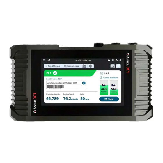
Page 24: Getting To Know The Homepage
The X1 system homepage provides essential information about the status of the production line, print station, and printheads, where users can quickly know what is happening through all these components. Each part of X1 system homepage is marked by a red number in the following Figure 1-15 and is described in the following Table 1-3. -
Page 25: Table 1-3. X1 System Homepage Settings
Settings Button: The quick access button leads to System Settings, where users can manage templates, files, and user accounts. Information about X1 controller is also provided. Information Display Button: It leads to the information display page to select the type of parameters of printer and cartridge to be displayed on the main page. - Page 26 Quick Edit Button: It allows quick adjustments to parameters while the printer is printing. Edit Message: Press it to enter X1 Message Editor. Please refer to Figure 1-17 and Table 1-4. Ink Cartridge Information: It shows information on the cartridge status. If a printhead is installed or connected, this icon will be colored, otherwise, it is black and white.
-
Page 27: Figure 1-16. X1 System Homepage - A Menu For More Settings
Besides main page shortcuts, press Menu button in the most upper-left corner to go to more settings of X1 controller. Figure 1-16. X1 System Homepage – A Menu for More Settings ANSER CODING INC. X1 User Interface... -
Page 28: Getting To Know The Message Editor
Getting to Know the Message Editor X1 offers the possibility to create and edit messages directly in the controller. The X1 editor offers the necessary tools to make message editing a more straightforward process. In X1 homepage, press “ ” to go to X1 message editor. Each part of the message editor is marked by a red number in the following Figure 1-17 and is described in the following Table 1-4. -
Page 29: Table 1-4. X1 Message Editor Settings
Table 1-4. X1 Message Editor Settings Item Icon Description Add Object Button: Using it to create a message is highly recommended. It contains the most commonly used objects: Text, Date/Time, Counter, Image, Barcode, Shape, Variables, and Shift. Press each object to go to further settings. - Page 30 Canvas Measurement Unit: It allows users to change the measurement unit of the canvas to millimeter, inch, or pixel. Message Settings Page: Display settings of messages being edited. After entering X1 Message Editor, this page is shown closed at the bottom. Press Toggle Buttons listed below to see the page.
-
Page 31: Adding Message Objects
1.4.1 Adding Message Objects In X1 Message Editor, use Add Object “ ” button is highly recommended to start message editing. Press it and the Add Object page appears as the figure below shows. Here you can see the most often-used objects are all included. Please refer to the following sections for step-by-step instructions of adding objects into a message. -
Page 32: Add Object: Text
1.4.1.1 Add Object: Text STEP 1: In X1 Message Editor, Press “Text” in the Add Object page, and the following page will show. Select a template and press OK. Select a template. Preview of selected template. Figure 1-19. Add Object – Select a Text Template ANSER CODING INC. -
Page 33: Figure 1-20. Add Object - Edit A Text
If the text or an object is not selected, it cannot be edited. Press it to edit text. Figure 1-21. Add Object – Format a Text ANSER CODING INC. X1 User Interface... -
Page 34: Figure 1-22. Add Object - Adjust Text Styles: Density, Stretching And Spacing
100% will go down vertically instead of up. 2. Press the field Angle in the upper right corner of message editing page to key in the desired angle of a selected text. ANSER CODING INC. X1 User Interface... -
Page 35: 1.4.1.1.1 Adjust Size And Position
Adjust Size of the text. Figure 1-23. Add Object – Adjust Text Size Press message name tag to go to Message Settings page. Adjust message height. Figure 1-24. Add Object – Adjust Message Height ANSER CODING INC. X1 User Interface... -
Page 36: Figure 1-25. Add Object - Hold To Adjust Message Position
X-axis and Y-axis fields. Figure 1-25. Add Object – Hold to Adjust Message Position X1 Message Editor provides eleven fonts and thirty-three system languages. Please see the following tables for details. Table 1-5. X1 Fonts Supported... -
Page 37: Table 1-6. X1 System Languages And Virtual Keyboards Supported
Table 1-6. X1 System Languages and Virtual Keyboards Supported Language English Translation System Language Virtual Keyboard ْ ُ ع َ ر َ ب ِ ي َّ ة �� �� ُ ُل Arabic �� �� Български Bulgarian �� �� Cрпски Serbian ��... -
Page 38: Add Object: Date/Time
If it’s zero then it’s a production date. Select Day, Month or Year. Press to key in the shelf life of your products. Figure 1-27. Add Object – Select Date/Time Template ANSER CODING INC. X1 User Interface... -
Page 39: Figure 1-28. Add Object - Date/Time Format Preference
STEP 3: If there is a Format Preference button, press it to select more format options of Date/Time. Figure 1-28. Add Object – Date/Time Format Preference STEP 4: Use the below Date/Time Settings page to arrange format and style of your date. Figure 1-29. Add Object – Date/Time Settings ANSER CODING INC. X1 User Interface... -
Page 40: 1.4.1.2.1 Add A Time Template
STEP 1: Go to Menu “ ” > Settings “ ” > Template Management. Press Date/Time Format Template. Figure 1-30. Add Object – Date/Time Template Management STEP 2: Press Add Template. Figure 1-31. Add Object – Add Time Template ANSER CODING INC. X1 User Interface... -
Page 41: Figure 1-32. Add Object - Add Time Digit
” to add desired digit into the template. And press Save. Press #@$% to add colons. Figure 1-32. Add Object – Add Time Digit STEP 4: Now you can select the Time template just created. Figure 1-33. Add Object – Select Time Template ANSER CODING INC. X1 User Interface... -
Page 42: Add Object: Barcode
Add Object: Barcode STEP 1: If you are at homepage, press Add Message “ ” > Add Object “ ” > Barcode. If you are at X1 Message Editor, press Add Object “ ” > Barcode to select Barcode Type. -
Page 43: Figure 1-36. Add Object - Barcode Content
STEP 4: And the barcode is inserted. Select the barcode to adjust more settings. Press message name tab to change settings of this message. Message Name Tab Figure 1-37. Add Object – Barcode Message ANSER CODING INC. X1 User Interface... -
Page 44: Add Object: Variables
Internal, External, or Database (when importing an Excel file). Figure 1-38. Add Object – Variables STEP 2: In the Variable page, select a template on the right-hand side and press OK. Figure 1-39. Add Object – Variables Page ANSER CODING INC. X1 User Interface... -
Page 45: Figure 1-40. Add Object - Variables Message
STEP 3: Adjust format and style in the Variables tab below and the GS1 data matrix variable is ready. Figure 1-40. Add Object – Variables Message ANSER CODING INC. X1 User Interface... -
Page 46: Add Object: Counter, Image, Shape, And Shift
STEP 1: Use ADD Object to insert Counter, Image, Shape or Shift. Figure 1-41. Add Object – Counter, Image, Shape and Shift STEP 2: Select a template. Figure 1-42. Add Object – Templates in Counter, Image, Shape and Shift ANSER CODING INC. X1 User Interface... -
Page 47: Figure 1-43. Add Object - Settings In Counter, Image, Shape And Shift
Figure 1-43. Add Object – Settings in Counter, Image, Shape and Shift STEP 4: Press Save button “ ” after adding objects and editing messages to go back to homepage. STEP 5: In homepage, select a message and production line and get ready to print. ANSER CODING INC. X1 User Interface... -
Page 48: Message Related Settings
Normal: Overwrite the upside-down printing settings in the print station. Upside Down: Print the message upside down. Height Message height based on the printhead height. Width Display the total width of the current message. Figure 1-44. Message Delay ANSER CODING INC. X1 User Interface... -
Page 49: Printing A Message
” to select a message, or go to the menu Messages > Create. Figure 1-45. Homepage (Production Line Page) STEP 2: Scroll down or use Search “ ” to find a previously edited message. And press Next. Figure 1-46. Select Message Page ANSER CODING INC. X1 User Interface... -
Page 50: Figure 1-47. Print Station Page
Or, you can press the button “ ” and switch to simplified view which gives option to quickly select a message for the working production line. Figure 1-48. Message Printing Page STEP 4: Finally, press Start to print the message. ANSER CODING INC. X1 User Interface... -
Page 51: Getting To Know The Device Configuration Page
The production line and print station page allow users to perform the following: • Create a production line. • Access production line settings. • Delete or duplicate a production line. • Import or export production line. ANSER CODING INC. X1 User Interface... -
Page 52: Figure 1-50. Add A Production Line
The Production Line & Print Station setting page displays parameters related to the production line on the left side of the panel. On the right, options of adding a Print Station are listed, as it shown in Figure 1-50 below. Figure 1-50. Add a Production Line Figure 1-51. Add a Print Station ANSER CODING INC. X1 User Interface... -
Page 53: Table 1-8. Production Line And Print Station Settings
Enable the option to use your own encoder. Users can manually input the diameter and PPR. DPI Converter Divide encoder DPI by 1 to 8. Calculated Output Show actual printout DPI calculated by diameter, PPR and DPI converter. ANSER CODING INC. X1 User Interface... -
Page 54: Print Station
Single Print Station Mode Some applications require to print content on two sides of a product that is running on one production line. X1 supports up to two single printheads which means users have the flexibility to set up two single head print stations within the same production line setup. -
Page 55: 1.5.2.1.1 Print Station Delay
1. Print station delay is set for all messages with a default value while message delay is set for individual message with higher priority; 2. When no message delay is set, X1 will use print station delay as message delay. Figure 1-54. Print Station Delay Note: The same delay value applies to all printing messages. -
Page 56: Stitch Print Station Mode
A production line can only have one print station in stitch mode since both of printheads are occupied. Figure 1-55. Add a New Print Station – Stitch Mode ANSER CODING INC. X1 User Interface... -
Page 57: Parallel Print Station Mode
1.5.2.3 Parallel Print Station Mode X1 parallel print station mode gives users a production without downtime. Two cartridges printing alternatively based on different ratios configured by the users. Software monitors cartridge levels and automatically switches to the second cartridge allowing the operator to replace the empty cartridge without needing to stop the production line. -
Page 58: Figure 1-57. Add A Parallel Print Station - Dual Color Printing Mode
Additionally, a parallel print station allows users to set “Dual Color” mode. In this mode, two ink color cartridges can be used to achieve the effect of printing one message with two different colors. In X1 message editor, you can put different parts of a message in different groups and each representing one color cartridge. -
Page 59: Printhead Settings
Press the Settings button to open the printhead settings page, as shown in Figure 1-58. Figure 1-58. Printhead Settings Overview Page Figure 1-59. Printhead Settings Page ANSER CODING INC. X1 User Interface... -
Page 60: Figure 1-60. Repeat Print - Initial Delay
Figure 1-60. Repeat Print – Initial Delay Note: 1. Initial Delay has top priority over message and print station delays. 2. Period value must be greater than the printing content total width. ANSER CODING INC. X1 User Interface... -
Page 61: External Devices
Figure 1-57. External Devices Page 1.5.4.1 Wi-Fi Wi-Fi menu displays options to connect the X1 controller to Wi-Fi hotspot. Please note that a USB-to-WiFi dongle is required. Supported model: TP Link TL-WN823N. Figure 1-58. Wi-Fi Settings Page ANSER CODING INC. -
Page 62: Ethernet
USB page displays the port settings for USB devices such as barcode scanners. X1 uses the USB interface as a serial virtual COM port to communicate with serial devices. Virtual COM port enables X1 to access a USB device as if it were a built- in serial port. -
Page 63: Scan Selector
RS-232 menu displays the settings for configuring the RS-232 port interface. Enable this setting when working with serial devices that communicate via RS-232 interface. Please refer to X1 Technical Specifications V1.7 for X1 M8 8-pin RS-232 pinout and definitions. 1.5.4.5 Scan Selector Figure 1-61. -
Page 64: Scan & Print
The data is contained into the variable objects which later can be used when creating a message. Scan & Print also permits to split the data into parts according to position and length of the serial data. ANSER CODING INC. X1 User Interface... - Page 65 RS-232 and ttyS04 for RS-485 when no device is connected or the scanner is not setup as virtual COM or CDC. ttyACM0 or ttyUSB0 will appear when X1 detects the serial device. Number of Scan Perform multiple scans, data is stored to variable1, variable2, up to 20.
-
Page 66: Scan & Select
Users define a rule that contains data key and the message to print. X1 compares whether the input data key is presented in the scan data or not. If the key matches, then X1 will assign the linked message to the production line. - Page 67 Select the message that will be selected if the Data Key matches the scan data. Data Key The data that is expected to be contained in the scan stream. Assigned Station Select one or two stations where users assign the message. Enable Check to enable the rule conditions. ANSER CODING INC. X1 User Interface...
-
Page 68: Getting To Know The Settings Page
Access System Settings page through main menu “ ” > Settings “ ”, or use the quick access button “ ” on the homepage. (Please see Figure 1-61.) 1.6.1 System Settings Figure 1-61. X1 System Settings Page ANSER CODING INC. X1 User Interface... -
Page 69: Table 1-11. X1 System Settings Description
Table 1-11. X1 System Settings Description Option Description System Language and It allows users to change system language and add multiple languages to the Keyboard Layout keyboard. Screen Settings It allows users to configure the following items: Display Test: Perform a test on the LCD panel. -
Page 70: Template Management
Can be used to store data sent by external devices. Format Preference Customize the name of the months used in production and expiry date objects. Template Shift Template Allow users to create a table of work shifts for different operators and hourly periods. ANSER CODING INC. X1 User Interface... -
Page 71: File Management
The file management page is a file center where users can manage all different types of files used throughout the systems. Here, users can import and export one or more files. The import and export process are done using USB. Figure 1-63. The File Management Page ANSER CODING INC. X1 User Interface... -
Page 72: User Management
Figure 1-64. The User Management Page The X1 system provides three default accounts (Admin, Manager, and Operator), and each has their respective access levels. (Please see Table 1-13.) Admin can edit options for each account, delete existing accounts, and add new ones. -
Page 73: Table 1-13. X1 User Accounts Management Table
Table 1-13. X1 User Accounts Management Table Access Level Admin Manager Operator �� �� �� Start / Stop / Select Message �� �� Create Message �� �� Delete Message �� �� Message Settings �� �� Edit Message �� �� Production Line and Print Station ��... -
Page 74: About Printer
(They can also be seen by pressing the cartridge icon). Options to reset the system to factory default, to restore the system from a backup, and to import/export can all be found in this page. ANSER CODING INC. X1 User Interface... -
Page 75: X1 Printing Setup
Production Line Setup Production line settings are the top layer of the X1 function structure (Please see Figure 1-61.), and they encapsulate print stations and messages. It is required for having a production line created before setting up print stations and selecting messages. -
Page 76: Print Station Setup
Repeat the same steps when an additional single print station is needed. Once it is ready, press Save and proceed to printhead settings. Note: In Stitch mode, the photocell sensor source should be set to the controller. ANSER CODING INC. X1 Printing Setup... -
Page 77: Printhead Settings
” button to access the selected printhead settings page. Set resolution, repeat settings and pre-purge. Press the Save button to save printhead settings. Note: When using a half-inch printhead, select one of the nozzle rows or both for nozzle switching. ANSER CODING INC. X1 Printing Setup... -
Page 78: Stitching Alignment
To align the printheads and print a complete message, the operator can perform physical adjustments to printhead installation, as well as, changing the stitch alignment settings directly in the X1 software. Perform an initial test print to confirm stitch alignment status. -
Page 79: Repeat Print Settings
For example, printing ten times, 10mm after triggering the photocell sensor, and leave a gap of 20mm between each repetition: Table 2-1. The Example of Repeat Print Settings Parameter Value Trigger Initial Delay 10mm Period 20mm Infinite Count ANSER CODING INC. X1 Printing Setup... -
Page 80: Pre-Purge Settings
Pre-purge releases drop of ink from time to time keeping nozzles moist when cartridge is idle (in printing mode but no printing). Users can define the time cycle (when) to purge the nozzles as well as the level (amount of ink drops) used per each purge. Please refer to Table 1-10. ANSER CODING INC. X1 Printing Setup... -
Page 81: Quick Edit
It is possible to make adjustments to printing related settings while a print station is in operation. Press the “ ” button on the homepage to access the Quick Edit settings page. Figure 2-3. Quick Edit Page – General and Counter ANSER CODING INC. X1 Printing Setup... -
Page 82: Figure 2-4. Quick Edit Page - Variable Input And Database
Variable 1 Figure 2-4. Quick Edit Page – Variable Input and Database ANSER CODING INC. X1 Printing Setup... - Page 83 Use together with changing the access level to achieve this purpose. D. Database: After an excel file (.csv) is imported, select the row from which to start printing. This setting will be applied after two prints. ANSER CODING INC. X1 Printing Setup...
-
Page 84: X1 Operation
Usage of the Variable Object X1 printer system enables users to set their own variables, such as company names, addresses, URL, product numbers, etc. For application required to quickly replace specific content of the message without modifying the whole message layout, “Variable”... -
Page 85: Internal Variable Table
Internal Variable Table There is a total of 100 variables that can be defined and kept in an X1 controller. Each of the variables can hold up to 100 alphabets (100 bytes). Message editor is full Unicode supported in UTF-8 format. -
Page 86: Data Update Using Communication Protocol (0Xca)
USB COM port. For a set of stream data, set the position and the length of the data needed for printing. Navigate to Device Configurations > External Devices: Scan&Print Figure 3-3. The Scan and Print Page ANSER CODING INC. X1 Operation... -
Page 87: Format Preferences
April نيسان Abril أيار Mayo June حزي ر ان Junio July تموز Julio August آب Agosto September أيلول Septiembre تش ر ين October األول Octubre تش ر ين November الثان Noviembre December األول كانون Diciembre ANSER CODING INC. X1 Operation... -
Page 88: Export And Import Data
Export and Import Data There are two ways to export and import data from the X1 system, and it can be done either in the About Printer menu or in the File Management menu. 3.3.1 About Printer Insert the memory into USB port. -
Page 89: Figure 3-5. To Import From Usb (1)
“Backup_xxxx” or “File_Management_xxxx”. Figure 3-5. To Import from USB (1) 3. Dig into the file folder and press Done, and the directory tree will show up. Figure 3-6. To Import from USB (2) ANSER CODING INC. X1 Operation... -
Page 90: Figure 3-7. To Import From Usb (3)
4. Select the files you want to import and press Done. Figure 3-7. To Import from USB (3) ANSER CODING INC. X1 Operation... -
Page 91: File And System Backup
File and System Backup To back up all system information on X1, be sure to insert a FAT32 format USB before starting the backup. Access About Printer > Restore & Backup by pressing the quick access button “ ” on the homepage and go to the About Printer menu. -
Page 92: I/O Management
Figure 3-9. External Devices Page 3.5.1 I/O Assign In I/O Assign, users can find all the events / actions that have been created. Here users can execute the following I/O functions. Figure 3-10. I/O Management Page ANSER CODING INC. X1 Operation... -
Page 93: I/O Edit
In main menu, go to Device Configurations > External Devices to see I/O Edit settings page as the folloing figure shows. Figure 3-11. I/O Edit Settings Page Figure 3-12. I/O Edit Settings Page – Event List (1) ANSER CODING INC. X1 Operation... -
Page 94: Figure 3-13. I/O Edit Settings Page - Event List (2)
Print Start: To monitor if printing started. E.g., pressing Start button. Input X1 M8 8-pin port, pin #8 (DIN). Please refer to X1 Technical Specifications V1.7. Input High: To monitor if input signal is high level. Input Low: To monitor if input signal is low level. -
Page 95: Table 3-4. I/O Edit Settings - Logical Operand Definition
Reset Counter: Reset object message counters (item, box and lot). Output X1 alarm port (M8 6-pin). Please refer to X1 Technical Specifications V1.7. Alarm Green: Set the output pin #6 signal status. Alarm Yellow: Set the output pin #4 signal status. -
Page 96: Figure 3-14. Action Settings - Digital Output
Figure 3-14. Action Settings – Digital Output ANSER CODING INC. X1 Operation... -
Page 97: Advanced Action Settings
Pulse Positive: Increase the output signal. Pulse Negative: Decrease the output signal. Delay: Set a delay in milliseconds before executing the digital output behavior. Pulse Duration: Set a time duration for the positive or the negative pulse options. ANSER CODING INC. X1 Operation... -
Page 98: Troubleshooting
Ink cartridge is empty. Please change a new cartridge. Ink Low The ink level is low (with 5% left) or lower than the custom trigger value. EDC Not Match Either the country code, area code or both codes don’t match controller EDC. ANSER CODING INC. Troubleshooting... -
Page 99: Status Definition
1. Can’t read DISC. 2. EDC error. 3. Can’t recognize DISC. 4. No legal DISC. 5. Ink type not supported. 6. Cartridge latch is not closed. 7. Printhead is disconnected. 8. Wiping reminder time up. ANSER CODING INC. Troubleshooting... -
Page 100: Printhead Led Status
No cartridges are inserted or detected. Cartridge Error / Ink Empty Ink Low Flashing No Power Discovery Mode Flashing Flashing Alternately flash 0.2s ON > 0.2s OFF > 0.2s ON > 1s OFF then repeat 10 times. ANSER CODING INC. Troubleshooting... -
Page 101: Appendix
1. Before it starts, please make sure that the USB is formatted as FAT32 and the size of the partition is under 32GB. 2. Create a new folder within the USB and name it as auprn. 3. Copy the software upgrade file into the USB://auprn folder. Note: Please remove ink cartridge(s) before firmware upgrade for X1 controller. ANSER CODING INC. Appendix... - Page 102 5. Press Upgrade to initiate the upgrade process. 6. X1 will reboot automatically once the upgrade process is completed. Please go to Menu > Settings > About Printer to confirm the firmware versions of printer and of printhead are both updated.
- Page 103 1. Copy the printhead upgrade file into the auprn directory, and make sure only this file is in the directory. Note: Please remove ink cartridge(s) before X1 printhead upgrade. 2. Insert the USB to the controller, and wait to confirm the prompt window.
- Page 104 3. Wait for the process to be completed and it might take several minutes. When done, please press Exit and then Yes to exit the printhead update mode. It will go back to login page. 4. Go to Menu > Settings > About Printer > Firmware Version, and P0 & P1 FPGA should be shown. ANSER CODING INC. Appendix...
- Page 105 ANSER CODING INC.
Need help?
Do you have a question about the X1 and is the answer not in the manual?
Questions and answers