Table of Contents
Advertisement
Quick Links
Advertisement
Table of Contents

Subscribe to Our Youtube Channel
Related Manuals for Anser X1


Summary of Contents for Anser X1
- Page 1 X1 Product Manual ENGLISH Version 1.5 June 2021 Copyright 2019 ANSER Coding Inc. The information contained herein is subject to change without notice. Reproduction, adaptation or translation without prior written permission is prohibited, except as allowed under the copyright laws.
-
Page 2: Table Of Contents
Printhead Bracket Installation ......................20 1.2.9 Cartridge Insertion & Removal ......................22 X1 USER INTERFACE ..............................23 Getting started with X1 User Interface ....................23 2.1.1 X1 wizard setup ..........................23 Getting to know the homepage ......................28 Getting to know the message editor ....................... 30 Getting to know the device configuration page .................. - Page 3 Template Management ........................42 2.5.3 File Management ........................... 43 2.5.4 User Management .......................... 44 2.5.5 About Printer..........................46 X1 Printing Setup ................................ 47 Production Line Setup ..........................47 Print Station Setup ..........................48 Printhead Settings ..........................48 3.3.1 Stitching Alignment ........................49 3.3.2 Repeat Print Settings ........................
- Page 4 Fault Messages and Warnings ......................... 61 Status Definition ............................. 61 Technical Specifications .............................. 63 X1 Hardware Specifications ........................63 6.1.1 X1 Controller ..........................63 6.1.2 Controller ports Pin Descriptions ....................66 6.1.3 X1 Printheads ..........................68 External Accessories Specifications ......................71 6.2.1...
- Page 5 Modified Table 2.4-3 initial delay and period description. V1.4 2021/6/2 Add power consumption detail to Figure 6.1-1. Add Inrush Current in controller specification. V1.5 2021/7/1 Update power specification. Update Table 2.4-3 pre-purge feature description. Update new Anser Logo and official url address. ANSER CODING INC.
-
Page 6: X1 Hardware
X1 HARDWARE Overview 1.1.1 Controller Overview Figure 1.1-1 Ports Description Ground Connection of ground cable. Power Button Power ON/OFF controller. Power Port Port for DC24V input. Print Head-1 Port for connecting printhead-1 and controller. Print Head-2 Port for connecting printhead-2 and controller. -
Page 7: Printhead Overview
DISC Module For reading the parameters stored in the cartridge chip. Pen Board Driver Pins Pins for driving the firing of the cartridge. Ground Use to ground the printhead (s) Table 1.1-2 ANSER CODING INC. -
Page 8: X1 Hardware Installation
X1 Hardware Installation 1.2.1 Unpacking List Items Figure 1.2-1 Figure 1.2-2 ANSER CODING INC. - Page 9 (M3xL10). Use to mount the front and middle sections when doing stitch and parallel printheads. C5(M3XL4.5) Use to mount the photocell holder. C6 (M3XL6) Use to mount the printhead frames for single, stitch and parallel modes. ANSER CODING INC.
-
Page 10: X1 Controller Bracket Installation
Use to mount the anti-shocks’s front side to the printhead. Table 1.2-1 Figure 1.2-3 1.2.2 X1 Controller Bracket Installation STEP1: Assemble the A02 bar into the A09 base by using two screw type C03 (add washer). Figure 1.2-4 ANSER CODING INC. - Page 11 Figure 1.2-6 STEP5: Mount the controller on the main bracket base by using the A06 bracket connector. After finding the desired position for the controller, use two C01 screw type and screw tightly both sides of the connector. ANSER CODING INC.
- Page 12 STEP6: Finally, connect the ground wire connector (yellow/green wire 18 AWG) to the chassis ground source located. Figure 1.2-8 Perform soft shutdown of the system using the shutdown button found in log out page, and then press power button to completely power off controller. ANSER CODING INC.
-
Page 13: Single Printhead
INCH PRINTHEAD RAME Figure 1.2-9 INCH PRINTHEAD FRAME Figure 1.2-10 1.2.4 Mounting Stitch Printheads TICH RINTHEADS STEP1: Mount the front and rear pins of one printhead in the second groove, as illustraded in below images. Figure 1.2-11 ANSER CODING INC. - Page 14 STEP3: Use two C4 type of screws to lock the middle section of the printheads as illustrated below. Figure 1.2-13 STEP4: Mount the half-inch stitch front plate as illustrated below, and use three C6 type of screw to lock it. Figure 1.2-14 ANSER CODING INC.
- Page 15 Figure 1.2-15 STEP2: Use one C4 type of screw to lock the front section of both printheads as illustrated below. Figure 1.2-16 STEP3: Use one C4 type of screw to lock the printheads as illustrated below. Figure 1.2-17 ANSER CODING INC.
-
Page 16: Mounting Parallel Printheads
STEP1: Mount the front and back pins of one printhead in the third groove, as illustraded in below images. Figure 1.2-19 STEP2: Use one C4 type of screw to lock the middle section of both printheads as illustrated below. ANSER CODING INC. -
Page 17: Mounting Printhead Sensor
STEP3: Mount the parallel front plate as illustrated below, and use three C6 type of screw to lock it. Figure 1.2-21 Note: Follow same steps to install one-inch parallel printhead plate. 1.2.6 Mounting Printhead Sensor STEP1: Place the sensor inside the holder, and use two C05 type of screw to lock it as illustrated below. ANSER CODING INC. - Page 18 STEP2: Mount the sensor holder on either side of the printhead by using two C05 type of screws. Figure 1.2-23 STEP3: Plug the sensor M4 male connector to either the printhead or controller M4 female connector. Figure 1.2-24 Note: Use the extension cable to connect photocell to the controller. ANSER CODING INC.
-
Page 19: Mounting The Anti-Shock Mechanism
STEP2: At the front of the anti-shock, use one C8 type of screw and insert it into the upper hole. STEP3: At the back of the anti-shock, use one C7 type of screw to lock it. Figure 1.2-25 RINTHEAD IGHT NSTALLATION Figure 1.2-26 ANSER CODING INC. -
Page 20: Printhead Bracket Installation
Figure 1.2-28 STEP3: Insert the B03 bar into the back of the printhead B04, and use four C04 (M3xL10) type to screw the bar and printhead together. Figure 1.2-29 ANSER CODING INC. - Page 21 Figure 1.2-30 STEP4: Connect the ground wire connector (yellow/green wire 18 AWG) to the chassis ground source located at the back of printhead. Figure 1.2-31 Power off the controller before removing or plugging any of printhead cables. ANSER CODING INC.
-
Page 22: Cartridge Insertion & Removal
Insert the cartridge after system has completed boot up (login page). Do not insert the cartridge vertically. EMOVING THE CARTRIDGE 1. Open the printhead latch 2. Position the cartridge at 45 angle and pull it out. Stop printing before removing the cartridge. ANSER CODING INC. -
Page 23: X1 User Interface
X1 wizard setup Upon powering up X1 for the first time, the system will prompt a login page (Figure 2.1.1) where the user can set up an admin account. The user can also import the settings directly from another X1 controller using the USB. - Page 24 Figure 2.1-2 Figure 2.1-3 ANSER CODING INC.
- Page 25 Output DPI Adjust the size and density of the printing message. Table 2.1-1 After setting up a production line, the next step is to assign a print station which can compose of one or two printheads. Figure 2.1-4 ANSER CODING INC.
- Page 26 Print Upside Down All messages are printed using upside down orientation Station Delay The distance (mm or inch) from the sensor trigge to the location on the product where the print starts. Please refer to Figure 2.4-6. Table 2.1-3 ANSER CODING INC.
- Page 27 Save the initial setup and confirm whether you want to proceed to the message editor or homepage (Figure 2.2-1). Figure 2.1-6 Figure 2.1-7 ANSER CODING INC.
-
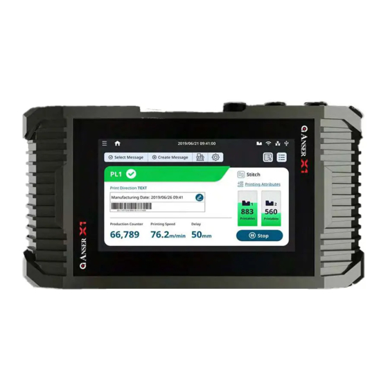
Page 28: Getting To Know The Homepage
Getting to know the homepage The X1 system homepage provides essential information about the status of the production line, print station, and printheads, where the user can quickly know what is happening through all the components. Figure 2.2-1 Figure 2.2-2... - Page 29 Start/Stop All production Line button Message List: Opens the select message list page where a new message can be set to print mode. Create New Message Button: Opens X1 on-board message editor. Device Configurations Button: Quick access button opens the Device Configuration menu.
-
Page 30: Getting To Know The Message Editor
Table 2.2-1 Getting to know the message editor X1 offers the possibility to create and edit messages directly in the controller. The X1 editor offers to the user the tools necessary to make message editing a more straightforward process. Figure 2.3-1... - Page 31 Message Settings: Display settings related to the message being edit. Access Message Settings Button: Press this button to access and display the configuration parameters of the current message. Toggle Button: Press this button to toggle down/up or hide the message settings window. Table 2.3-1 ANSER CODING INC.
- Page 32 Upside Down: Print the message upside down orientation. Height Message height based on the printhead height. Width Display the width of the current message considering the object furthest to the right side. Table 2.3-2 Figure 2.3-2 ANSER CODING INC.
-
Page 33: Getting To Know The Device Configuration Page
Figure 2.4-1 The production line & Print station page allows user to perform the following: Create a production line Access production line settings Delete or duplicate a production line Import or export production line ANSER CODING INC. - Page 34 The Production Line & Print station settings page display parameters related to the production line on the left side of the panel and the option to add Print Station on the right side, as shown in Figure 2.4-2. Figure 2.4-2 Figure 2.4-3 ANSER CODING INC.
-
Page 35: Print Station
Some applications require to print content on two sides of a product that it is running on one production line. X1 supports up to two single printheads which means the user has the flexibility to set up two single head print stations within the same production line setup. - Page 36 User must measure the distance from the sensor trigger point to the location on the product where to start the print, and the measurement should include the separation from sensor installation to the cartridge nozzle. Figure 2.4-6 Note: The same delay value applies to all the printing messages. ANSER CODING INC.
- Page 37 2.4.2.3 Parallel Print Station Mode X1 parallel print station mode gives the user a production without downtime. Two cartridges printing alternatively based on different ratios configured by the user. Software monitor cartridge level and automatically switch to the second cartridge allowing the operator to replace the empty cartridge without needing to stop the production.
-
Page 38: Printhead Settings
On the right side of the settings page, listed all the printhead setup related to existing print stations, and on the left side, an overview of the parameters related to the selected print station. Pressing the settings button (Figure 2.4-9) opens the printhead settings page, as shown in Figure 2.4-10. ANSER CODING INC. - Page 39 Figure 2.4-10 Figure 2.4-11 ANSER CODING INC.
- Page 40 Custom: manually set the time and level parameters to purge the nozzles Interval: the time in seconds to start a purge cycle. Level: Refer to the frequency of pre-purge cycle. The higher the level, the shorter time for each purge cycle. Table 2.4-3 ANSER CODING INC.
-
Page 41: Getting To Know The Settings Page
Note2: Period value must be greater than the printing content total width. Getting to know the Settings page Access through the main menu or the quick access System button found on the home page (see Figure 2.5-1), leads to the settings menu. 2.5.1 System Settings Figure 2.5-1 ANSER CODING INC. -
Page 42: Template Management
When a template is imported into a message, a copy is created of that template. Even if the template were deleted, it won’t affect the copy contained within the messages. ANSER CODING INC. -
Page 43: File Management
The file management page is a file center where users can manage all different types of files used throughout the systems. Here, users can import and export one or more files. The import and export process done using USB. ANSER CODING INC. -
Page 44: User Management
Navigate to system > User Management (Figure 2.5-4) from the menu tree. Figure 2.5-4 The X1 system provides three default accounts (Admin, Manager, and Operator), each with their respective access levels (Table 2.5-3). Admin can edit options for each account, delete existing accounts, and add new ones. - Page 45 User Management Report Restore/Backup/Reset About Printer Import/Export/ Printer Settings Table 2.5-3 Note: The default password for Admin is Admin, Manager is Manager and Operator is 0000. ANSER CODING INC.
-
Page 46: About Printer
(also seen by pressing cartridge icon). Options to reset the system to factory default, restore the system from a backup and options to import and export can all be found in this page. ANSER CODING INC. -
Page 47: X1 Printing Setup
Production Line Setup Production Line settings are the top layer of the X1 function structure (Figure 2.5-1), and they encapsulate print stations and messages. It is required for having a production line created before setting up print stations and selecting messages. -
Page 48: Print Station Setup
Set resolution, repeat settings and pre-purge Press the Save button to save printhead settings. Note: When using a half-inch printhead, select one of the nozzle rows or both for nozzle switching ANSER CODING INC. -
Page 49: Stitching Alignment
To align the printheads and print a complete message, the operator can perform physical adjustments to printhead installation, as well as, changing the stitch alignment settings directly in the X1 software. Perform an initial test print to confirm stitch alignment status. -
Page 50: Pre-Purge Settings
Pre-purge releases drop of ink from time to time keeping nozzles moist when cartridge idle (in printing mode but no printing). The user can define the time cycle to purge the nozzles as well as the level (amount of ink drops) used per each purge. Please Table 2.4-3. ANSER CODING INC. -
Page 51: Creating A Print Message
SAVE button to save and go back to the home page. Note: Printhead 1 is always the printhead at the bottom when using stitch printheads ANSER CODING INC. -
Page 52: Quick Edit
Quick Edit It is possible to make adjustments to printing related settings while a print station is in operation. Press the button on the home page to access the Quick Edit settings page. ANSER CODING INC. - Page 53 Figure 3.5-1 ANSER CODING INC.
- Page 54 Use together with access level to achieve this purpose. D. Database: After an excel (.csv) is imported, select from which row to start printing. Setting is applied after two prints. ANSER CODING INC.
-
Page 55: X1 Operation
X1 Operation Usage of the variable (string) Object X1 printer system enables users to set their own variables, such as Company name, addresses, URL, product number, etc. For application required to quickly replace specific content of the message without modifying the whole message layout, Variable is the right object to be used. -
Page 56: Internal Variable Table
Internal Variable Table There is a total of 100 variables that can be defined and kept in an X1 controller. Each of the Variables can hold up to 100 alphabets (100 bytes). Message editor is full Unicode support in UTF-8 format. -
Page 57: Format Preference
Figure 4.1-3 Format Preference Navigate to “Settings > Template Management > Format Preference Template” Create custom inputs for each month of the year. Refer to Table 4.2-1 Customized Month Figure 4.2-1 ANSER CODING INC. -
Page 58: Export & Import Data
Diciembre Table 4.2-1 Export & Import Data There are two ways to export and import data from the X1 system, it can be done either from the "About Printer" menu or from the "File Management" menu. About Printer Insert the memory into the USB port Press the "Import / Export"... - Page 59 2. Insert the USB into the USB port, click “Import” then access the directory of the USB where the files to import are located. Backup_xxxx or File_Management_xxxx. Figure 4.3-1 3. Dig into the file folder and press Done, the directory tree will show up. Figure 4.3-2 ANSER CODING INC.
-
Page 60: File & System Backup
Figure 4.3-3 File & System Backup To back up all system information on X1. Be sure to insert a FAT32 formatted USB before starting the backup. Access “About Printer > Restore & Backup” by pressing the quick access button on the home page, then going to the “About Printer”... -
Page 61: Troubleshooting
Open Wi-Fi Setting Page Ethernet Click icon show Error message Dialog, Click See more Open Ethernet Setting Page. Cartridge Click icon show Error message Dialog, Click Open Ink Error String & Error Code. Click icon show Error message. Table 5.2-1 ANSER CODING INC. - Page 62 Cartridge no inserted or no detected Cartridge error/Ink Empty ON Ink Low Flashing No Power Alternately flash 0.2s ON > 0.2s OFF > 0.2s ON Discovery Mode Flashing Flashing 1s OFF then repeat 10 times Table 5.2-3 ANSER CODING INC.
-
Page 63: Technical Specifications
6. Digital I/O port (1 IN & 4 OUT pins) 7. Encoder port x 1 8. Sensor port x 1 Communication Protocols TCP IP/UDP, Modbus TCP, and ANSER RS485 protocols Dimensions & Weight 291 x 142 x 52mm / 2.12 Kg Operating Conditions... - Page 64 AC Power line: line to line ±1KV line to earth : ± 2KV DC Power line : line to earth : ± 0.5KV Performance Criteria B IEC61000-4-5 High-frequency continuous 3.0 Vrms (0.15~80Mhz) Performance Criteria A conducted immunity Table 6.1-1 ANSER CODING INC.
- Page 65 CONTROLLER DIMENSIONS ANSER CODING INC.
-
Page 66: Controller Ports Pin Descriptions
Sensor signal White : 23V ~ 24V : 0V ~ 12V Encoder signal Green : 23V ~ 24V : 0V ~ 12V DC 24V encoder/sensor Min : 20 V , Max : 24 V, 120mA Table 6.1-2 ANSER CODING INC. - Page 67 : 0V ~ 0.3V, 80mA RS485 - Yellow RS485 + Orange Min : 20 V , Max : 24 V, 120mA Brown : 20V ~ 24V Purple : 23V ~ 24V : 0V ~ 12V Table 6.1-4 ANSER CODING INC.
-
Page 68: X1 Printheads
6.1.3 X1 Printheads RINTHEAD PECIFICATIONS Items Description Printing Technology High Resolution Thermal Ink Jet Printhead Type Type H-0.5 & Type H-1.0 Print Height Type H-0.5: Single Print Head: 12.7mm Stitch Print Head: 12.7mm x 2 @ 24.75mm Type H-1.0: Single Print Head: 25.4mm (1.0 inch) Stitch Print Head: 12.7mm x 2 @ 48.7mm... - Page 69 RINTHEAD IMENSIONS ANSER CODING INC.
- Page 70 & B RINTHEAD RACKETS ANSER CODING INC.
-
Page 71: External Accessories Specifications
200 mm Circumference Power supply 10 – 30 VDC, max 100 mA Open Circuit Load Max 40 mA / channel Weight Approx. 1100 g Protection Rating IP67 Operating -10 °C up to +50 °C Temperature Table 6.2-1 ANSER CODING INC. - Page 72 NCODER IMENSIONS ANSER CODING INC.
-
Page 73: Photocell Sensor
10 to 30 VDC, 34mA or less Current Consumption Enclosure Rating IEC: IP67/NEMA: 4A, 6, 12/DIN:IP69K Temperature & -20 to +55 °C -4 to 131 °F (No freezing), 35 to 85 % RH (No Humidity condensation) Table 6.2-2 HOTOCELL IMENSIONS ANSER CODING INC. -
Page 74: Alarm Beacon
Items Description Height & Diameter 65mm x 70mm Protection Category IP65 Operating -30°C ~ +50°C Temperature Product Weight 1 g (one level) Operating Voltage 24V DC Operational & inrush 40mA & 250mA current Light Source Table 6.2-3 ANSER CODING INC. - Page 75 LARM EACON IMENSIONS ANSER CODING INC.
-
Page 76: Appendix
4. Insert the USB in one of the USB port and wait for the upgrade confirmation window to show up 5. Press the upgrade button to initiate the upgrade process 6. X1 will reboot automatically once the upgrade process is completed. Note: Access the “About Printer” page to confirm both printer and printhead firmware versions are updated. - Page 77 3. Wait for the process to be completed, might take several minutes. When done, please press “Exit” and then “Yes” to exit the printhead update mode. It will back to login page. Access about printer > firmware version, P0 & P1 FPGA should show ANSER CODING INC.
- Page 78 ANSER CODING INC.
Need help?
Do you have a question about the X1 and is the answer not in the manual?
Questions and answers
need a part #
The part number for the Anser X1 is ANS1001.
This answer is automatically generated
my anser x1 is not printing , it moves goes up and down but it wont print. How do i troubelshoot this or what can i check to fic this issue. Thank You
To troubleshoot printing issues with the Anser X1:
1. Check LED indicators: Ensure the “Alarm” and “Ink Low” icons are not illuminated. Confirm that the “Run” icon is pulsing. Press the “Print On” key on the remote control to light up the “Print” icon.
2. Fix clogged nozzles: Remove the ink cartridge, gently clean the nozzle with a lint-free wipe using a downward motion. Two separate lines of ink should appear on the wipe after cleaning.
3. Use pre-purge settings: Enable pre-purge to keep nozzles moist in hot and dry environments. Set the purge time cycle and ink amount to maintain print quality.
4. Perform Quick Edit: Adjust printing settings by pressing the “Quick Edit” button on the homepage while the print station is operating.
5. Ensure setup completion: Confirm the production line and message settings are properly saved. Without these, message editing and printing cannot start.
This answer is automatically generated