Table of Contents
Advertisement
Quick Links
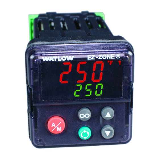
EZ-ZONE
Users Manual
PID Controller
1241 Bundy Boulevard., Winona, Minnesota USA 55987
Phone: +1 (507) 454-5300, Fax: +1 (507) 452-4507 http://www.watlow.com
0600-0065-0000 Rev. D
April 2010
Warranty
®
The EZ-ZONE
PM is manufactured by ISO
9001-registered processes and is backed by a
three-year warranty to the first purchaser for use,
providing that the units have not been misap-
plied. Since Watlow has no control over their use,
and sometimes misuse, we cannot guarantee
against failure. Watlow's obligations hereunder,
at Watlow's option, are limited to replacement,
repair or refund of purchase price, and parts which
upon examination prove to be defective within the
warranty period specified. This warranty does not
apply to damage resulting from transportation,
alteration, misuse or abuse. The purchaser must
use Watlow parts to maintain all listed ratings.
Technical Assistance
If you encounter a problem with your Watlow
Controller, review your configuration information
to verify that your selections are consistent with
your application: inputs, outputs, alarms, limits,
etc. If the problem persists, you can get technical
assistance from your local Watlow representative
(see back cover), by e-mailing your questions to
wintechsupport@watlow.com or by dialing +1
(507) 494-5656 between 7 a.m. and 5 p.m., Central
Standard Time (CST). Ask for an Applications
Engineer. Please have the following information
available when calling:
• Complete model number
• All configuration information
• User's Manual
• Factory Page
Return Material Authorization (RMA)
1. Call Watlow Customer Service, (507) 454-
5300, for a Return Material Authorization
(RMA) number before returning any item for
repair. If you do not know why the product
failed, contact an Application Engineer or
Product Manager.
The EZ-ZONE PM Controller User's Manual is
copyrighted by Watlow Winona, Inc., © April
2010 with all rights reserved. The EZ-ZONE PM is
covered by U.S. Patent No. 6,005,577 and Patents
Pending
Overview
The EZ-ZONE PM Express controllers take the pain
out of solving your thermal loop requirements
while reducing the cost of control-loop ownership.
You can order this control as a single loop PID
controller with a high-amperage power output in
either a 16
th
or 32
nd
DIN panel-mount package.
It just got a whole lot easier to solve the ther-
mal requirements of your system. Because the
EZ-ZONE family of controls are highly scalable
®
PM Express
SATISFACTION
ISO 9001
Registered Company
Winona, Minnesota USA
Made in the U.S.A.
where you pay only for what you need. So if you
are looking for a single or multi-loop PID control-
ler, an over-under limit controller or an integrated
controller (PID and Limit), the EZ-ZONE family of
controls can meet all of your needs. Point your
browser to http://www.watlow.com to find out
more about the EZ-ZONE family of controls.
For this particular control, serial communications
is accomplished using Watlow's Standard Bus
protocol. If the need arises to network your con-
trols and communicate using other popular proto-
®
cols such as Modbus RTU/TCP
, EtherNet/IP
DeviceNet
TM
or Profibus DP consider using the
EZ-ZONE family Remote User Interface/Gateway
(RUI/GTW).
Safety Information
We use note, caution and warning symbols throughout
this book to draw your attention to important opera-
tional and safety information.
A "NOTE" marks a short message to alert you to an
important detail.
A "CAUTION" safety alert appears with information
that is important for protecting your equipment and
performance. Be especially careful to read and follow
all cautions that apply to your application.
A "WARNING" safety alert appears with informa-
tion that is important for protecting you, others and
equipment from damage. Pay very close attention to
all warnings that apply to your application.
The electrical hazard symbol,
triangle) precedes an electric shock hazard CAUTION
or WARNING safety statement. Further explanations
follow:
Symbol
TOTAL
CUSTOMER
3 Year Warranty
1 2
3 4
Installation and Wiring
Dimensions 1/32 DIN
15.9 mm
0.63 in
TM
,
22.4 mm
(0.88 in)
(a lightning bolt in a
Explanation
CAUTION – Warning
or Hazard that
needs further ex-
planation than label
on unit can provide.
Consult users
manual for further
information.
ESD Sensitive
product, use proper
grounding and
handling techniques
when installing or
servicing product.
Unit protected by
double/reinforced
insulation for shock
hazard prevention.
Do not throw in
trash, use proper
recycling techniques
or consult manu-
facturer for proper
disposal.
Unit can be powered
with either alternat-
ing current (ac)
voltage or direct
current (dc) voltage.
101.6 mm
4.00 in
31.2 mm
30.9 mm
1.23 in
1.22 in
Side
Top
45.2 mm
(1.78 in)
Recommended panel spacing
panel thickness 1.53 to 9.52 mm
(0.060 to 0.375)
21.6 mm
(0.85 in)
1/32 DIN Maximum Cutout
Unit is a
Listed device
per Underwriters
Laboratories®. It
has been evaluated
to United States and
Canadian require-
ments for Process
Control Equipment.
UL 61010 and CSA
C22.2 No. 61010.
File E185611 QUYX,
QUYX7. See:
www.
ul.com
Unit is a Listed
device per Under-
writers Laborato-
ries®. It has been
evaluated to United
States and Canadian
requirements for
Hazardous Loca-
tions Class 1 Divi-
sion II Groups A,
B, C and D. ANSI/
ISA 12.12.01-2007.
File E184390 QUZW,
QUZW7. See:
www.
ul.com
Unit is compliant
with European
Union directives.
See Declaration
of Conformity for
further details on
Directives and
Standards used for
Compliance.
Unit has been
reviewed and
approved by Fac-
tory Mutual as a
Temperature Limit
Device per FM Class
3545 standard.
See:
www.fmglobal.
com
Unit has been
reviewed and
approved by CSA
International for
use as Temperature
Indicating-Regu-
lating Equipment
per CSA C22.2 No.
24. See:
www.csa-
international.org
53.3 mm
2.10 in
Front
21.6 mm
(0.85 in)
Advertisement
Table of Contents

Related Manuals for Watlow EZ-ZONE PM Express


Summary of Contents for Watlow EZ-ZONE PM Express
- Page 1 International for Winona, Minnesota USA use as Temperature 1241 Bundy Boulevard., Winona, Minnesota USA 55987 Indicating-Regu- lating Equipment Phone: +1 (507) 454-5300, Fax: +1 (507) 452-4507 http://www.watlow.com per CSA C22.2 No. 24. See: www.csa- international.org 0600-0065-0000 Rev. D Made in the U.S.A.
- Page 2 Dimensions 1/16 DIN Installation 15.8 mm (0.62 in) 101.6 mm 53.3 mm (4.00 in) (2.10 in) Removing the Mounted Controller from Its Case 53.3 mm (2.10 in) 1. From the controller's face, pull out the tab on each side until you hear it click. 1. Make the panel cutout using the mounting Side Front template dimensions in this chapter.
- Page 3 Power Supply Note: Note: Switched dc and Process outputs use a common power supply with a maximum current output of 40mA. In the drawings below for each input notice that the Slot A connector labeling is identified. As an example, supplied current (mA) from output 1 and 2 can be 20/20, 30/10, 40/0, 10/30, etc... Note: Outputs When using a 2 wire RTD, jumper S1 and T1 together...
- Page 4 Upon power up of the control, using Operations Menu the advance key will scroll through the & 32 DIN PID Controller various prompts found in the Operations Menu. At any point within the Operations Range (Defaults are shown bold) Display Parameter Name Description menu to return to the default display push the Infinity key.
- Page 5 To enter the Setup Menu push and hold Setup Menu the up and down arrow keys for ap- & 32 DIN PID Controller proximately 3 seconds. Once there, push the green advance key to scroll through Display Parameter Name Description Range (Defaults are shown bold) to the prompt of choice and then use the up and down arrow keys to change Function of Output 2...
- Page 6 - 0 to 10VÎ(dc) into a minimum 1,000Ω load • Auto-tune control algorithm - 4 to 20mA into maximum 800Ω load Multilingual User Manuals (PID only) and associated Watlow part numbers: • Control sampling rates: input = 10Hz, outputs = Operator Interface...
Need help?
Do you have a question about the EZ-ZONE PM Express and is the answer not in the manual?
Questions and answers