Table of Contents
Advertisement
Quick Links
User's Manual
User Levels:
• New User ....................................................... go to page 1.1
• Experienced User .......................................... go to page 2.1
• Expert User .................................................... go to page 2.1
Installers:
• Installation ...................................................... go to page 2.1
• Wiring .............................................................go to page 3.1
1241 Bundy Blvd., P.O. Box 5580, Winona, Minnesota USA 55987-5580, Phone: (507) 454-5300, Fax: (507) 452-4507
WO97-XUMN Rev A
July 1997
Series 97
Watlow Controls
ISO 9001
Registered Company
Winona, Minnesota USA
Made in the U.S.A.
$15.00
Advertisement
Chapters
Table of Contents

Related Manuals for Watlow 97 series


Summary of Contents for Watlow 97 series
- Page 1 • Wiring .............go to page 3.1 ISO 9001 Registered Company Winona, Minnesota USA Watlow Controls 1241 Bundy Blvd., P.O. Box 5580, Winona, Minnesota USA 55987-5580, Phone: (507) 454-5300, Fax: (507) 452-4507 Made in the U.S.A. WO97-XUMN Rev A July 1997...
- Page 2 Your comments or suggestions on this manual are welcome. Please send them to: Technical Writer, Watlow Controls, 1241 Bundy Blvd., P.O. Box 5580, Winona, MN 55987-5580; phone: (507) 454-5300; fax: (507) 452-4507. The Series 97 User’s Manual is copyrighted by Watlow Winona, Inc., © July 1997, with all rights reserved. (1134)
-
Page 3: Table Of Contents
Series 97 Table of Contents Chapter 1: Overview ..... . .1.1 Figures and Tables Chapter 2: Installation ..... .2.1 Inputs and outputs . - Page 4 SATISFACTION We stand behind our product and are committed to your total satisfaction. Pictured below are some of the people at Watlow who have worked hard to bring you one of the finest industrial temperature controllers available today. Included in the photo are members of the development team, production team, and representatives from our core manufacturing and customer service areas.
-
Page 5: Input 2
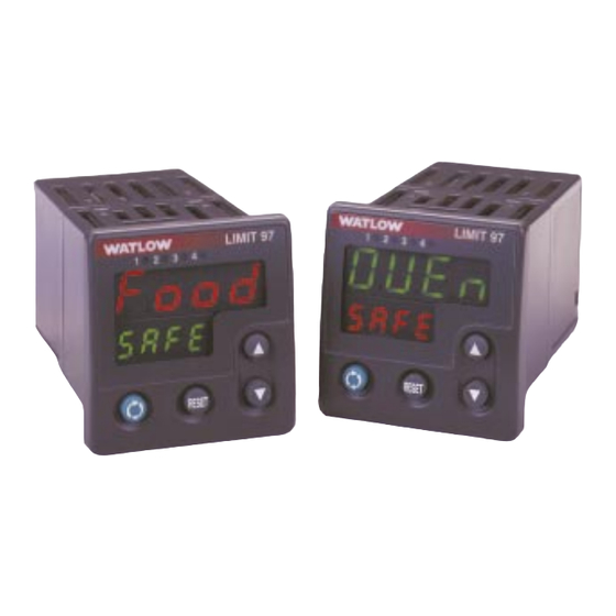
Overview Introduction Watlow’s Series 97 is a microprocessor-based controller with a single input, second auxiliary input and four outputs. Input 1 is used to measure temperature from a sensor. Input 2 can be utilized as a remote reset switch or a hardware lockout switch. With up to four outputs, the controller is versatile in handling applications that require a high/low limit, alarms, retransmit and communications. - Page 6 Setup Steps What to do How to do it See Chapter Two. Install the controller. Wire the controller. See Chapter Three. Configure the controller for Chapter Four explains the keys, displays and software your application. navigation. Chapter Five explains features, such as alarms and control methods.
-
Page 7: Chapter 2: Installation
Chapter Two Installation 2.050" 1.77" to 1.79" (44.96mm to 45.47mm) LIMIT 97 Panel Cutout Panel 1.77" to 1.79" Thickness 2.050" (44.96mm to 45.47mm) 0.06" to 0.38" (1.5 to 9.7 mm) RESET 0.540" (13.72mm) Minimum 0.310" (7.874mm) Figure 2.1 - Series 97 multiple panel cutout dimensions. NOTE: Measurements between panel cutouts are the minimum recommended. - Page 8 Installing the Series 97 Controller Installing and mounting requires access to the back of the panel. 1. Make the panel cutout using the tear-out mounting template found on the previous page, or the dimensions found in this chapter. 2. Check to see that the gasket is properly seated into the gasket channel on the front bezel and that it is not twisted.
-
Page 9: Removing The Controller
Removing the Series 97 Controller Hold the controller with one hand while using the other hand to loosen the screws with a #2 Phillips screwdriver until the end of the screw is flush or past the end of the can- tilevers, see the figure below. - Page 10 Notes 2 . 4 I nst a l lat i on Wat l o w Se r i e s 9 7...
-
Page 11: Chapter 3: Wiring
Chapter Three Wiring Power Wiring ..... .3.3 Sensor Installation Guidelines ..3.3 Wiring Example ....3.4 Wiring Notes . -
Page 12: Isolation Blocks
Wiring the Series 97 Wiring options depend on the model number. Check the terminal designation stickers on either side of the controller and compare your model number to those shown here and with the model number breakdown on the inside back cover of this manual. NOTE: Using the Diagnostics Menu (Factory Page) check Output 1 Hardware through Output 4 Hardware, [Oty1] through [Oty4]. -
Page 13: Power Wiring
Power Wiring ç 100 to 240VÅ (ac), nominal (85 to 264 actual) 97 A _ - _ _ _ _ - _ _ _ _ 24 to 28V‡ (ac/dc), nominal (21 to 30 actual) 97 B _ - _ _ _ _ - _ _ _ _ CAUTION: If high voltage is applied to a low-voltage unit,... -
Page 14: Wiring Example
Wiring Example ∫ç 120VÅ (ac) WARNING: high temperature To avoid potential light electric shock and fuse high limit mechanical coil contactor damage to property and equipment, use National Electric Code (NEC) 15 (+) 13 (-) safety practices when DIN-a-mite DA1C-1624-C000 wiring and connecting optional normally open... -
Page 15: Wiring Notes
Wiring Notes ∫ç Sketch in your application on this page or a copy of it. See the wiring example in this chapter. WARNING: To avoid damage to property and equipment, and/or injury of loss of life, use National Electric power Code (NEC) standard wiring practices to install and operate the... -
Page 16: Input 1
Input 1 Wiring NOTE: – Thermocouple Successful installation Figure 3.6a requires five steps: Available on all units • Choose the controller’s Impedance: 20MΩ hardware configuration and model number (Appendix); • Choose a sensor (Chapters 3 and 6, and Appendix); • Install the controller (Chapter 2);... -
Page 17: Output 1
(relay coils, solenoids, etc.) with the mechanical relay, switched dc or solid-state relay output options requires use of an R.C. suppressor. Watlow carries the R.C. suppressor Quencharc brand name, which is a trademark of ITW Pakron. Watlow Part No. 0804- 0147-0000. -
Page 18: Output 2
Switched DC 30mA solid-state relay output options requires use of an R.C. suppressor. Open collector configuration: Watlow carries the R.C. Maximum voltage: 42VÎ (dc) suppressor Quencharc Maximum current: 200 mA brand name, which is a trademark of ITW Pakron. Watlow Part No. 0804- 0147-0000. -
Page 19: Output 3
(relay coils, solenoids, etc.) with the mechanical relay, switched dc or solid-state relay output options requires use of an R.C. suppressor. Watlow carries the R.C. suppressor Quencharc brand name, which is a trademark of ITW Pakron. Watlow Part No. 0804- 0147-0000. -
Page 20: Output 4
EIA/TIA-232 EIA/TIA-485 Retransmit Option Watlow carries the R.C. 97 _ _ - _ _ _ R - _ _ _ _ 97 _ _ - _ _ _ U - _ _ _ _ 97_ _ - _ _ _ M - _ _ _ _... - Page 21 NOTE: Successful installation Figure 3.11a — EIA-232 to EIA-485 Conversion requires five steps: • Choose the controller’s hardware configuration and model number T-/R- TD (A) (Appendix); T+/R+ TD (B) • Choose a sensor COM. RD (A) (Chapters 3 and 6, and RD (B) Appendix);...
- Page 22 Notes 3 . 1 2 W ir i n g Wa tl o w Se r i e s 9 7...
- Page 23 Chapter Four Navigation and Software Keys and Displays ....4.2 Navigation ......4.3 Software Map .
-
Page 24: Keys And Displays
Keys and Displays This chapter explains keys, displays and navigation skills, and presents charts showing how to accomplish basic and advanced tasks. You’ll also find a complete software map. Active Output (1-4) Indicator Lights: Lit when the corresponding output trips. Indicator light next to number 4 will flicker during communications activity if the communications option is used. - Page 25 Navigating the Series 97 Choose a page (Operations, Setup or Factory) and press its key sequence. The page appears in the lower display. LIMIT 97 LIMIT 97 RESET RESET • Operations Page: press ¿ and ¯ keys together for three seconds. LIMIT 97 LIMIT 97 RESET...
-
Page 26: Navigation
Navigation Home Page [``97] Process Value [Safe] Limit Status ‰ and RESET ¿ and ¯ [LIM] Limit Menu for 6 seconds for 3 seconds [OPEr] Operations Page Operations Page [InP1] Input 1 Menu ¿ and ¯ [`SEt] Setup Page for 3 seconds ¿... - Page 27 [InP1] Input 1 Menu Setup Page Factory Page [`SEt] [`SEt] Setup Page [`LOC] Lockout Menu [SEn1] Sensor Type 1 ¿ ‰ [FctY] ¯ [In`1] Input 1 ¿ [Fcty] Factory Page [rL`1] Range Low 1 ‰ [OPEr] Operations Page Mode ¯ [rh`1] Range High 1 [`SEt] Setup Page Lock [dEC1] Decimal 1...
- Page 28 Tip: Use the foldout software map on the inside back cover for easy reference. Basic navigation for new users Use this example task to learn how to use the keys and displays. Navigation skills are essential for setting up the controller. For more information about the control features available in the Series 97, see Chapter Five.
-
Page 29: Chapter 5: Features
Chapter Five Features Limit ......5.2 Input Calibration Offset ....5.3 Filter Time Constant . -
Page 30: Limit
Limit The Series 97 limit controller is added to thermal applications to limit over- or under-tem- perature conditions. The Series 97 controller provides safety assurance against instances where a high temperature runaway condition could occur from a shorted input sensor or an output device that could fail in a closed position. -
Page 31: Input
Input Calibration Offset Calibration offset allows a device to compensate for an inaccurate sensor, lead resistance or other factors that affect the input value. A positive offset increases the input value, and a negative offset decreases the input value. The input 1 offset value can be viewed or changed with Calibration Offset 1 [CAL1] (Limit Menu). -
Page 32: Filter Time Constant
Filter Time Constant A time filter smooths an input signal by applying a first-order filter time constant to the signal. Either the displayed value or both the displayed and control values can be filtered. Filtering the displayed value makes it easier to monitor. View or change the input 1 time filter with Filter Time Constant 1 [Ftr1] (Input 1 Menu). -
Page 33: Sensor Ranges
Sensor Selection You need to configure a controller to match the input device, which is normally a thermo- couple or RTD. When you select an input device the controller automatically sets the input linearization to match the sensor. It also sets high and low limits, which in turn limit the range high and range low values. -
Page 34: Event Inputs
Event Input With an event input an operator can perform certain operations on a system by opening or closing a switch or applying a dc logic signal to the controller. This feature can add conve- nience, safety or security to a system. Use Event Input Status [E`St] (Monitor Menu) to read the state of the event input para- meter. - Page 35 Retransmit The retransmit output can be used to transmit an analog signal representing the value of the input process variable. The retransmit signal can be configured as either a milliamp or a voltage signal. In choosing the type of retransmit signal the operator must take into account the input impedance of the external device and the required signal type, either volt- age or milliamps.
-
Page 36: Alarms
Alarms An alarm takes some action, usually notifying an operator, when the process temperature leaves a defined range. A user can configure how and when an alarm is triggered and whether it turns off automatically when the alarm condition is over. Alarm Set Points The alarm high set point defines the temperature that will trigger a high side alarm. -
Page 37: Alarm Latching
Process A process alarm uses one or two absolute set points to define an alarm condition. The alarm process value of output 2 can be viewed or changed with Alarm 2 High [A2hi] and Alarm 2 Low [A2Lo] (Alarm Menu). Alarm Latching A latched alarm will remain active after the alarm condition has passed. -
Page 38: Alarm Silencing
Alarm Silencing Alarm silencing has two uses: 1. It is often used to allow a system to warm up after it has been started up. With alarm silencing on, an alarm is not triggered when the process temperature is initially lower than the alarm low set point. -
Page 39: Communications
Communications Overview A Series 97 controller can also be programmed and monitored by connecting it to a personal computer or programmable logic controller (PLC) via serial communications. To use this communications option, a Series 97 must be equipped with an output 4 communications board for EIA/TIA-485 (97_ _ - _ _ _U - _ _ _ _), which allows as many as 32 controllers on a 4,000-foot-long network, or EIA/TIA-232 (97_ _ - _ _ _R - _ _ _ _), which allows a single con- troller to be connected to a computer. - Page 40 Notes 5 . 1 2 Fea t u r es Wat l o w Se r i e s 9 7...
- Page 41 Chapter Six Parameters Parameter Setup Order ....6.2 Home Page ..... . .6.3 Operations Page .
- Page 42 Changing this Affects this °C or °F [`C-F] Table 6.2 — Set up Output 1 [Ot`1] parameters in this Output 2 [Ot`2] order. Output 3 [Ot`3] Output 4 [Ot`4] Sensor Type [Sen1] Input 1 [In`1] Range High 1 [rh`1] Range Low [rL`1] Decimal 1 [DeC1] Calibration Offset 1 [Cal1] Input Software Filter 1 [Ftr1]...
-
Page 43: Home Page
Home Page The resting-state display shows the following set of data. The first prompt appears in the top display, the second in the bottom. Display Parameter Range Default Modbus Conditions for Address Parameters to Appear read/write [``97] Active: Always Upper Display [safe] Lower Display Monitor the processes... -
Page 44: Operations Page
Operations Page The operations page contains three menus: Display Parameter Range Default Modbus Conditions for Address Parameters to Appear read/write [Oper] Operations Page [Mon] Monitor [LIM] Select [LIM] Limit [Alm] Alarm (if any Go to an operations alarms are active) menu. -
Page 45: Limit Menu
Display Parameter Range Default Modbus Conditions for Address Parameters to Appear read/write [LIM] Limit Menu [Oper] Operations Page [L`Lo] Low Limit Set [`rL1] to [L`hi] -1 [`rL1] 701 r/w Active: Always Point Sets the low limit point. [L`hi] High Limit Set [L`Lo] +1 to [`rh1] [`rh1] 702 r/w... - Page 46 Display Parameter Range Default Modbus Conditions for Address Parameters to Appear read/write [A3hi] Alarm 3 High Process: Process: high 341 r/w Active if Output 3 (Output 3 Menu) is [``AL] (Alarm), Alarm 3 Low +1 to limit of Sets the high alarm Alarm Sides 3 (Output 3 Menu) high limit of selected selected...
-
Page 47: Setup Page
Setup Page The setup page contains 8 menus. Display Parameter Range Default Modbus Conditions for Address Parameters to Appear read/write [`Set] Setup Page [InP1] Input 1 [InP1] Active if Setup Page Lock [Inp2] Input 2 (if (Lockout Menu) is not set to Go to a setup menu. - Page 48 Display Parameter Range Default Modbus Conditions for Address Parameters to Appear read/write [rL`1] Range Low 1 602 r/w Active if Setup Page Lock (Lockout Menu) is not set to Sets the input range [hide]. low. This setting is the lowest value that the set point can have.
-
Page 49: Input 2 Menu
Display Parameter Range Default Modbus Conditions for Address Parameters to Appear read/write [Inp2] Input 2 Menu [`set] Setup Page [In`2] Input 2 [`OFF] off: (0) 611 r/w Active if input 2 hardware is [E`In] Event Input: present (97 _1 _-_ _ _ _ -_ _ _ _) Sets the input type and Setup Page Lock (Lockout parameter of input... - Page 50 Display Parameter Range Default Modbus Conditions for Address Parameters to Appear read/write [hys2] Alarm Hysteresis 1 to 9999 720 r/w Active if Output 2 is enabled, hardware is present (not 97 _ _-_ A _ _-_ _ _ _ ), Output 2 Sets the switching (Output 2 Menu) is set to hysteresis for the...
-
Page 51: Output 3 Menu
Display Parameter Range Default Modbus Conditions for Address Parameters to Appear read/write [Out3] Output 3 Menu [`set] Setup Page [Ot`3] Output 3 [`OFF] off (0) [`OFF] 734 r/w Active if Output 3 hardware is [``AL] alarm (1) present (97 _ _-_ _ D _-_ _ _ _), Selects type of Output 3 (Output 3 Menu) is output 3. -
Page 52: Output 4 Menu
Display Parameter Range Default Modbus Conditions for Address Parameters to Appear read/write [Anu3] Alarm [``no] no (0) [`Yes] 742 r/w Active if Output 3 hardware is Annunciation 3 [`Yes] yes (1) present (97 _ _-_ _ D _-_ _ _ _), Output 3 (Output 3 Menu) is Selects alarm 3 set to [``AL] (Alarm) and... - Page 53 Display Parameter Range Default Modbus Conditions for Address Parameters to Appear read/write [Lgc4] Alarm Logic 4 [al`0] alarm condition [al`0] none* Active if Output 4 is equipped for de-energizes output a relay (97 _ _-_ _ _ D-_ _ _ _), Selects alarm 4 [al`C] alarm condition Output 4 (Output 4 Menu) is...
-
Page 54: Display Menu
Display Parameter Range Default Modbus Conditions for Address Parameters to Appear read/write [Addr] Address 1 to 247 none* Active if Output 4 is equipped for communications (96 _ _-_ _ _ R- Sets _ _ _ _ or 96 _ _-_ _ _ U-_ _ _ _) communications and Setup Page Lock (Lockout address. - Page 55 Display Parameter Range Default Modbus Conditions for Address Parameters to Appear read/write [UP`L] Upper Display 0: _ [____] 1401 r/w Active if Upper Display [UdSP] is User Limit 1: A 1402 r/w set to [USEr]. Message 2: b 1403 r/w 3: C 1404 r/w Select four...
-
Page 56: Global Menu
Display Parameter Range Default Modbus Conditions for Address Parameters to Appear read/write [LdSP] Lower Display [L`St] limit status [L`St] 1405 r/w Active: Always. (0):[SAFE]; [``hi]; Selects the value or [``lo] message that will [USEr] user message appear in the lower display. -
Page 57: Factory Page
Factory Page The factory page contains four menus: Display Parameter Range Default Modbus Conditions for Address Parameters to Appear read/write [fcty] Factory Page [`LOC] Lockout Menu [cin1] Active: Always Selection [dIag] Diagnostics Menu Choose factory menu [cin1] Calibration 1 to enter. Menu [cout] Process Output Calibration Menu... - Page 58 Display Parameter Range Default Modbus Conditions for Address Parameters to Appear read/write [`Sn1] Serial Number 1 0 to 9999 none Active: Always Reads the first four digits of the serial number. [`Sn2] Serial Number 2 0 to 9999 none Active: Always Reads the last four digits of the serial number.
- Page 59 Display Parameter Range Default Modbus Conditions for Address Parameters to Appear read/write [tout] Test Output [none] none (0) [none] 1514 r/w Active: Always [Out1] Output 1 (1) Turns on specific [Out2] Output 2 (2) output. [Out3] Output 3 (3) [Out4] Output 4 (4) [all`] all outputs (5) [DISP] Test Display [`OFF] turn off cyclical...
-
Page 60: Input Calibration Menu
Display Parameter Range Default Modbus Conditions for Address Parameters to Appear read/write [cin1] Input Calibration Menu [Fcty] Factory Page [`rSt] Restore Factory [``no] No (0) [``no] 1601 w Active if Calibration Lock Calibration [`yes] Yes (1) (Lockout Menu) is not set to [hide] Restores factory calibration (Stores... -
Page 61: Output Calibration Menu
Display Parameter Range Default Modbus Conditions for Address Parameters to Appear read/write [cout] Output Calibration Menu [Fcty] Factory Page [4``4] Output 0.00 to 99.99 4.00 1619 w Active if Output 4 is process (97 _ Calibration 4, _-_ _ _ M-_ _ _ _) and Calibration Lock (Lockout Menu) is not set to [hide] Enter the output... - Page 62 Notes NOTE: For more information about how parameter settings affect the controller’s operation, see Chapter Five, Features. 6 . 22 P a ra m e te r s Watl o w Se r i e s 9 7...
-
Page 63: Appendix
Appendix Troubleshooting Alarms and Errors ..A.2 Modbus™ RTU ....A.4 Modbus Address Chart ... . .A.10 Calibrating the Series 97 . -
Page 64: Troubleshooting Alarms And Errors
Troubleshooting Alarms and Errors Indication Probable Cause(s) Power • No power. • Power to unit may be off. • Fuse may be blown. • Breaker may be tripped. • Safety interlock door switch etc. may be activated. • Wiring may be open. •... - Page 65 • Check the communication card documentation for setable variables and operational testing. • Restart COMS software and check for settings agreement. Verify the COM bus is active. • Verify operation with Watlow comms tool. • Check sensor connections. • Check sensor connections and sensor wiring.
- Page 66 Modbus Remote Terminal Unit (RTU) Modbus RTU enables a computer or PLC to read and write directly to registers containing the controller’s parameters. With it you could read all 141 of the controller’s parameters with five read commands. Because of the wide array of choices available for setting up a Series 97 controller, only a subset of the prompts contain parameters in a given situation.
- Page 67 Packet format: | nn | nn | nn nn… | nn nn | ∆ ∆ ∆ ∆ ∆ ∆ address command registers and/or data Read Multiple Registers Command (0x03 or 0x04) This command returns from 1 to 32 registers. Packet sent to controller:| nn | 03 | nn nn | 00 nn | nn nn | ∆...
- Page 68 Example: Read register 0 (model number) of the controller at address 1. Sent: 01 03 00 00 00 01 84 0A Received: 01 03 02 03 DC B9 2D Message: 988 (0x03DC). Example: Read register 1 and 2 (Process 1 and 2 values) of controller at address Sent: 05 03 00 01 00 02 94 4F Received:...
- Page 69 Packet sent to controller: | nn | 10 | nn nn | 00 01 | 02 | nn nn | nn nn | ∆ ∆ ∆ ∆ ∆ ∆ ∆ ∆ ∆ ∆ ∆ controller address (one byte) write to multiple registers command (0x10) starting register high byte starting register low byte number of registers to write high byte (0x00)
- Page 70 Example: Run loop back test on controller at address 40 (0x28). Sent: 28 08 55 66 77 88 31 B7 Received: 28 08 55 66 77 88 31 B7 Exception Responses When a controller cannot process a command it returns an exception response and sets the high bit (0x80) of the command.
- Page 71 Cyclical Redundancy Checksum (CRC) Algorithm This C routine, calc_crc(), calculates the cyclical redundancy checksum, CRC, for a string of characters. The CRC is the result of dividing the string by 0xA001. Modbus applications calculate the packet’s CRC then append it to the packet.
- Page 72 Modbus Register Numbers Absolute Relative Parameters Absolute Relative Parameters 40001 Model Number 41402-41405 1401-1404 Upper Display User 40002 Serial Number 1 Limit Message (4 characters) 40003 Serial Number 2 41406 1405 Lower Display 40004 Software ID Number 41407- 41410 1406-1409 Lower Display User Safe Message 40005 Software Revision (4 characters)
- Page 73 Calibrating the Series 97 To enter the a calibration menu, first warm up the unit, then enter the Factory Page by holding down the Reset Key and ‰ for six seconds. Once in the Factory Page [Fcty] use the up-arrow ¿ or down-arrow ¯ key to select a menu. The last two menus on the Factory Page are Input Calibration Menu [cin1] and Output Calibration Menu [cout].
- Page 74 Thermocouple Input Procedure Equipment • Type J reference compensator with reference junction at 32°F/0°C, or type J thermocouple calibrator to 32°F/0°C. • Precision millivolt source, 0 to 50mV minimum range, 0.002mV resolution. Input 1 Setup and Calibration 1. Connect the correct power supply to terminals 8 and 9 (see Chapter Three and the Appendix).
- Page 75 Set RTD Calibration, 380Ω [r380] (Input Calibration Menu) to [`yES]. Press the Advance Key ‰ to store the 380.00Ω input and move to the next prompt. 7. Rewire for operation and verify calibration. Process Output Procedures Equipment • Precision volt/ammeter with 3.5-digit resolution. Output 4 Setup and Calibration 1.
-
Page 76: Glossary
Glossary annunciator — A visual display that uses pilot lights to indicate the former or existing condition of several items in a system. burst fire — A power control method that repeatedly turns on and off full ac cycles. Also called zero-cross fire, it switches close to the zero-voltage point of the ac sine wave. -
Page 77: Modbus™ Rtu
hysteresis — A change in the process variable required to re-energize the control or alarm output. Sometimes called switching differential. integral — Control action that automatically eliminates offset, or droop, between set point and actual process temperature. See auto-reset. integral control (I) — A form of temperature control. The I of PID. See integral. - Page 78 proportional band (PB) — A range in which the proportioning function of the control is active. Expressed in units, degrees or percent of span. See PID. proportional control — A control using only the P (proportional) value of PID control. range —...
- Page 79 WatLink — A Watlow software application for configuring and communication with Watlow controllers via a EIA-485 network and a Microsoft Windows- compatible personal computer. zero cross — Action that provides output switching only at or near the zero- voltage crossing points of the ac sine wave.
-
Page 80: Specifications
Specifications Electromechanical Relay • Form C contact configuration (1135) • Minimum load current 10mA @ 5VÎ (dc) • Rated resistive and inductive loads: 2A @ 250VÅ (ac) or Controller 30VÎ (dc) maximum • Microprocessor-based, user selectable control modes • Electrical life 100,000 cycles at rated current •... - Page 81 Communications Terminals • EIA/TIA-485, EIA/TIA-232 •Touch safe • Opto-isolated •22 to 12 AWG • Modbus RTU protocol ™ • 1200, 2400, 4800, 9600, 19200 baud rates Power • 32 maximum units can be connected (With additional 485 •100-240VÅ (ac) +10%, -15%; 50/60Hz, ±5% repeater hardware, up to 247 units may be connected) •24-28VÅ...
-
Page 82: Ordering Information
Ordering Information (1136) 9 7 — — - — — — — - — — — — Series 97 Microprocessor-based ⁄ DIN with universal input 1. Options include: software, power supply, input 2, four outputs and display color Power Supply = 100-240VÅ... -
Page 83: Index
Index Calibration Menu Lock 6.17 Input Calibration Menu 6.19-6.21, Calibration Offset 5.3, 6.5 A.12 Channel 1 A-D Counts 6.19 Input Error Latching 6.16 Channel 2 A-D Counts 6.19 Inputs and outputs 1.1 configure the controller 4.6 Input Software Filter 1 6.8 communications 5.11 Input-to-output isolation 3.2 Address 6.14... - Page 84 Serial Number 2 6.18 Set Ground 6.20 Operations Page 4.4 Setup Page 4.5 Operations Page menus 6.4-6.6 Setup Page Lock 6.17 Operations Page Mode Lock 6.17 Setup Page menus 6.7-6.16 ordering information A.20 setup steps 1.2 Output 2 6.9 Silencing 2 6.10 Output 3 6.11 Silencing 3 6.11 Output 4 6.12...
-
Page 85: Prompt Index
Prompt Index [Up`l] Upper Display User Limit Message 6.15 [Lat2] Latching 2 6.10 [Lat3] Latching 3 6.11 [Lat4] Latching 4 6.12 [4``1] Output Calibration 4, 1V 6.21 [LdSp] Lower Display 6.16 [4``4] Output Calibration 4, 4mA 6.21 [lead] Lead Resistance Calibration 6.20 [4`10] Output Calibration 4, 10V 6.21 [L9c2] Alarm Logic 2 6.10 [4`20] Output Calibration 4, 20mA 6.21... - Page 86 Notes A.2 4 A ppe nd ix Watl ow Ser ie s 97...
-
Page 87: Alarm Silencing
Changing this Affects this °C or °F [`C-F] Table 6.2 — Set up Output 1 [Ot`1] parameters in this Output 2 [Ot`2] order. Output 3 [Ot`3] Output 4 [Ot`4] Sensor Type [Sen1] Input 1 [In`1] Range High 1 [rh`1] Range Low [rL`1] Decimal 1 [DeC1] Calibration Offset 1 [Cal1] Input Software Filter 1 [Ftr1]... - Page 88 Series 97 Fold-out Software Map Setup Page Home Page Factory Page [InP1] [``97] Input 1 Menu Process Value [`SEt] Setup Page [`LOC] Lockout Menu [Safe] Limit Status [SEn1] Sensor Type 1____________ [FctY] Factory Page [In`1] Input 1 __________________ [OPEr] Operations Page Mode _______ [rL`1] Range Low 1 _____________ [`SEt] Setup Page Lock ___________ [rh`1] Range High 1 _____________...
- Page 89 • A restocking charge of 20% of the net price is charged for all standard units returned to stock. Your Authorized Watlow Distributor is: Watlow Series 97 User’s Manual Watlow Controls, 1241 Bundy Blvd., P.O. Box 5580, Winona, MN 55987-5580, Phone: (507) 454-5300, Fax: (507) 452-4507...
Need help?
Do you have a question about the 97 series and is the answer not in the manual?
Questions and answers