Table of Contents
Advertisement
Quick Links
INSTRUCTION MANUAL
NPN DISCRETE INPUT MODULE, 16 points
(Tension clamp terminal block)
BEFORE USE ....
Thank you for choosing us. Before use, please check con-
tents of the package you received as outlined below.
If you have any problems or questions with the product,
please contact our sales office or representatives.
■ PACKAGE INCLUDES:
NPN discrete input module ................................................(1)
■ MODEL NO.
Confirm Model No. marking on the product to be exactly
what you ordered.
■ INSTRUCTION MANUAL
This manual describes necessary points of caution when
you use this product, including installation, connection and
basic maintenance procedures.
POINTS OF CAUTION
■ CONFORMITY WITH EU DIRECTIVES
• The equipment must be mounted inside a panel.
• The actual installation environments such as panel con-
figurations, connected devices, connected wires, may af-
fect the protection level of this unit when it is integrated
in a panel system. The user may have to review the CE
requirements in regard to the whole system and employ
additional protective measures to ensure the CE conform-
ity.
■ GENERAL PRECAUTIONS
• Before you remove or mount the unit, turn off the power
supply and input signal for safety.
• Switches on the side of the module can be set for mainte-
nance only while the power supply is off. Do not access
them while the power is supplied.
■ ENVIRONMENT
• Indoor use.
• When heavy dust or metal particles are present in the
air, install the unit inside proper housing with sufficient
ventilation.
• Do not install the unit where it is subjected to continuous
vibration. Do not subject the unit to physical impact.
• Environmental temperature must be within -10 to +55°C
(14 to 131°F) with relative humidity within 30 to 90% RH
in order to ensure adequate life span and operation.
■ WIRING
• Do not install cables close to noise sources (relay drive
cable, high frequency line, etc.).
• Do not bind these cables together with those in which
noises are present. Do not install them in the same duct.
■ EXCITATION SUPPLY
• Input connector: Rated current 3 A DC (rated current 3
A for internal fuse (slow blow fuse i
MG CO., LTD. www.mgco.jp
5-2-55 Minamitsumori, Nishinari-ku, Osaka 557-0063 JAPAN
t (A
sec) max. 5.04).
2
2
MODEL
■ AND ....
• The unit is designed to function as soon as power is sup-
plied, however, a warm up for 10 minutes is required for
satisfying complete performance described in the data
sheet.
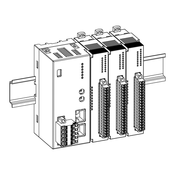
INSTALLATION
■ HOW TO MOUNT THE MODULE ON DIN RAIL
• I/O Module
Confirm that the locking clamps of the I/O module are set.
Insert the module in parallel to the next one while aligning the grooves of
both modules (A & B in the above figure).
Maintain it perpendicularly to the rail.
More I/O modules can be added in the same manner.
R80DAT16A2
A
B
EM-7031 Rev.1 P. 1 / 5
Advertisement
Table of Contents

Related Manuals for MG R80DAT16A2


Summary of Contents for MG R80DAT16A2
- Page 1 • Input connector: Rated current 3 A DC (rated current 3 A for internal fuse (slow blow fuse i t (A sec) max. 5.04). EM-7031 Rev.1 P. 1 / 5 MG CO., LTD. www.mgco.jp 5-2-55 Minamitsumori, Nishinari-ku, Osaka 557-0063 JAPAN...
- Page 2 Note 2: I/O modules cannot hold tightly on the DIN rail by themselves without power/network module. Secure them to the position if necessary by using DIN rail end plates. EM-7031 Rev.1 P. 2 / 5 MG CO., LTD. www.mgco.jp 5-2-55 Minamitsumori, Nishinari-ku, Osaka 557-0063 JAPAN...
- Page 3 Di12 Input 12 Without (*) Di13 Input 13 With Di14 Input 14 Di15 Input 15 Di16 Input 16 Exc. supply 0V Exc. supply 24V EM-7031 Rev.1 P. 3 / 5 MG CO., LTD. www.mgco.jp 5-2-55 Minamitsumori, Nishinari-ku, Osaka 557-0063 JAPAN...
- Page 4 Connect the unit as in the diagram below. ■ EXTERNAL DIMENSIONS unit: mm [inch] 72 [2.83] (4 [.16]) 24 [.94] (3 [.12]) 55 [2.17] DIN rail (35 mm wide) EM-7031 Rev.1 P. 4 / 5 MG CO., LTD. www.mgco.jp 5-2-55 Minamitsumori, Nishinari-ku, Osaka 557-0063 JAPAN...
- Page 5 • AI0,5−10WH 0.5 mm (Phoenix Contact) • AI0,75−10GY 0.75 mm² (Phoenix Contact) • A1−10 1.0 mm² (Phoenix Contact) • A1,5−10 1.5 mm² (Phoenix Contact) EM-7031 Rev.1 P. 5 / 5 MG CO., LTD. www.mgco.jp 5-2-55 Minamitsumori, Nishinari-ku, Osaka 557-0063 JAPAN...
Need help?
Do you have a question about the R80DAT16A2 and is the answer not in the manual?
Questions and answers