Advertisement
INSTRUCTION MANUAL
DC VOLTAGE INPUT MODULE
(8 points, isolated, tension clamp terminal block)
BEFORE USE ....
Thank you for choosing us. Before use, please check con-
tents of the package you received as outlined below.
If you have any problems or questions with the product,
please contact our sales office or representatives.
■ PACKAGE INCLUDES:
DC voltage input module ....................................................(1)
■ MODEL NO.
Confirm Model No. marking on the product to be exactly
what you ordered.
■ INSTRUCTION MANUAL
This manual describes necessary points of caution when
you use this product, including installation, connection and
basic maintenance procedures.
POINTS OF CAUTION
■ CAUTION
• If the equipment is used in a manner not specified by this
manual, the protection provided by the equipment may
be impaired.
■ CONFORMITY WITH UL APPROVAL
• This equipment is suitable for use in Installation Catego-
ry II and in a Pollution Degree 2 environment.
• Altitude up to 2000 meters.
• Install inside an industrial control panel or equivalent for
UL.
• Make sure the used Power/Network module is the UL
approval that is appropriately evaluated with this equip-
ment.
■ CONFORMITY WITH EU DIRECTIVES
• The equipment must be mounted inside a panel.
• The actual installation environments such as panel con-
figurations, connected devices, connected wires, may af-
fect the protection level of this unit when it is integrated
in a panel system. The user may have to review the CE
requirements in regard to the whole system and employ
additional protective measures* to ensure the CE con-
formity.
* For example, installation of noise filters and clamp fil-
ters for the power source, input and output connected to
the unit, etc.
■ POWER REQUIRMENTS
• The equipment receives power through the internal cir-
cuit and confirms its operational range as indicated below:
Internal Power: 5V DC, ≤ 200mA
MG CO., LTD. www.mgco.jp
5-2-55 Minamitsumori, Nishinari-ku, Osaka 557-0063 JAPAN
MODEL
■ GENERAL PRECAUTIONS
• Before you remove or mount the unit, turn off the power
supply and input signal for safety.
• Do not touch the connector while the power is supplied.
Static electricity may cause a malfunction.
• Switches on the side of the module can be set for mainte-
nance only while the power supply is off. Do not access
them while the power is supplied.
■ ENVIRONMENT
• Indoor use.
• When heavy dust or metal particles are present in the
air, install the unit inside proper housing with sufficient
ventilation.
• Do not install the unit where it is subjected to continuous
vibration. Do not subject the unit to physical impact.
• Environmental temperature must be within -10 to +55°C
(14 to 131°F) with relative humidity within 30 to 90% RH
in order to ensure adequate life span and operation.
■ WIRING
• Do not install cables close to noise sources (relay drive
cable, high frequency line, etc.).
• Do not bind these cables together with those in which
noises are present. Do not install them in the same duct.
■ AND ....
• The unit is designed to function as soon as power is sup-
plied, however, a warm up for 10 minutes is required for
satisfying complete performance described in the data
sheet.
R8-SVT8
EM-9668 Rev.4 P. 1 / 6
Advertisement
Table of Contents

Related Manuals for MG R8-SVT8


Summary of Contents for MG R8-SVT8
- Page 1 • The equipment receives power through the internal cir- cuit and confirms its operational range as indicated below: Internal Power: 5V DC, ≤ 200mA EM-9668 Rev.4 P. 1 / 6 MG CO., LTD. www.mgco.jp 5-2-55 Minamitsumori, Nishinari-ku, Osaka 557-0063 JAPAN...
-
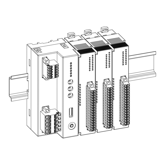
Page 2: Installation
Maintain it perpendicularly to the rail. When removing the cover, pull it out while squeezing the hooks inward. More I/O modules can be added in the same manner. EM-9668 Rev.4 P. 2 / 6 MG CO., LTD. www.mgco.jp 5-2-55 Minamitsumori, Nishinari-ku, Osaka 557-0063 JAPAN... - Page 3 2) I/O modules cannot hold tightly on the DIN rail by themselves without power/network module. Secure them to the position if necessary by using DIN rail end plates. EM-9668 Rev.4 P. 3 / 6 MG CO., LTD. www.mgco.jp 5-2-55 Minamitsumori, Nishinari-ku, Osaka 557-0063 JAPAN...
-
Page 4: Component Identification
CONFIGURATION MODE SW2-8 DIP switch setting (*) PC Configurator and communication Note: Be sure to set unused SW2-3 through 2-5 and 2-7 to OFF. EM-9668 Rev.4 P. 4 / 6 MG CO., LTD. www.mgco.jp 5-2-55 Minamitsumori, Nishinari-ku, Osaka 557-0063 JAPAN... -
Page 5: Terminal Connections
Connect the unit as in the diagram below. ■ EXTERNAL DIMENSIONS unit: mm (inch) [3 (.12)] 72 (2.83) [4 (.16)] 24 (.94) 55 (2.17) DIN RAIL (35 mm wide) EM-9668 Rev.4 P. 5 / 6 MG CO., LTD. www.mgco.jp 5-2-55 Minamitsumori, Nishinari-ku, Osaka 557-0063 JAPAN... -
Page 6: Wiring Instructions
(AWG17) (Phoenix Contact) • A1,5-10 1.5 mm (AWG15) (Phoenix Contact) INPUT 5 – INPUT 6 – INPUT 7 – INPUT 8 – *1. Not used. EM-9668 Rev.4 P. 6 / 6 MG CO., LTD. www.mgco.jp 5-2-55 Minamitsumori, Nishinari-ku, Osaka 557-0063 JAPAN...
Need help?
Do you have a question about the R8-SVT8 and is the answer not in the manual?
Questions and answers