Advertisement
Quick Links
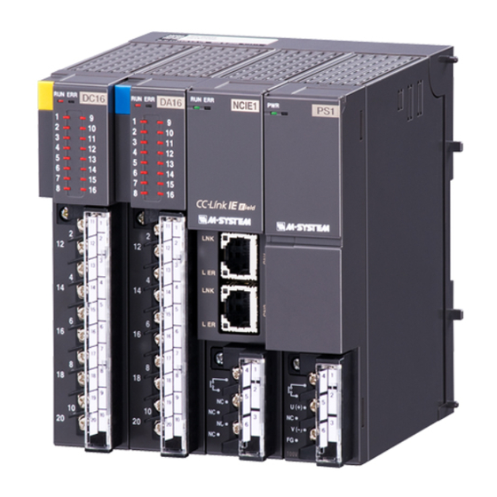
INSTRUCTION MANUAL
NETWORK INTERFACE MODULE
(CC-Link IE Field network)
BEFORE USE ....
Thank you for choosing us. Before use, please check con-
tents of the package you received as outlined below.
If you have any problems or questions with the product,
please contact our sales office or representatives.
■ PACKAGE INCLUDES:
Network interface module ..................................................(1)
■ MODEL NO.
Confirm Model No. marking on the product to be exactly
what you ordered.
■ INSTRUCTION MANUAL
This manual describes necessary points of caution when
you use this product, including installation, connection and
basic maintenance procedures.
POINTS OF CAUTION
■ CONFORMITY WITH EU DIRECTIVES
• The equipment must be mounted inside the instrument
panel of a metal enclosure.
• The actual installation environments such as panel con-
figurations, connected devices, connected wires, may af-
fect the protection level of this unit when it is integrated
in a panel system. The user may have to review the CE
requirements in regard to the whole system and employ
additional protective measures to ensure the CE conform-
ity.
■ HOT SWAPPABLE MODULES
• The module can be replaced while the power is ON. Be
sure to replace it when the module is not communicat-
ing with a host, as it may affect the system. Replacing
multiple modules at once may greatly change line voltage
levels. We highly recommend to replace them one by one.
■ GENERAL PRECAUTIONS
• DO NOT set the switches while the power is supplied.
The switches are used only for maintenance without the
power.
■ ENVIRONMENT
• Indoor use.
• When heavy dust or metal particles are present in the
air, install the unit inside proper housing with sufficient
ventilation.
• Do not install the unit where it is subjected to continuous
vibration. Do not subject the unit to physical impact.
• Environmental temperature must be within -10 to +55°C
(14 to 131°F) with relative humidity within 30 to 90% RH
in order to ensure adequate life span and operation.
MG CO., LTD. www.mgco.jp
5-2-55 Minamitsumori, Nishinari-ku, Osaka 557-0063 JAPAN
MODEL
■ WIRING
• Do not install cables close to noise sources (relay drive
cable, high frequency line, etc.).
• Do not bind these cables together with those in which
noises are present. Do not install them in the same duct.
• Be sure to attach the terminal cover for safety.
INSTALLATION
Use the Installation Base Model R3-BS, or Model R3-BSW
for free I/O address capability.
Before mounting the Network Interface Module onto the
Base, be sure to configure the module as explained below.
■ DATA ALLOCATION
The setting determines the data area size assigned to each
I/O module mounted on the base.
The data sent/received via CC-Link IE Field is mapped ac-
cording to this setting.
See "COMPONENT IDENTIFICATION" and "TRANSMIS-
SION DATA DESCRIPTIONS".
■ STATION No., ETC.
See "COMPONENT IDENTIFICATION".
■ NETWORK SLOTS ON THE BASE
I/O 1
I/O 2
With Model R3-BS base, mount the I/O Modules from the
left end (I/O 1) to the right in order that the Network Mod-
ule assigns data areas from I/O 1.
Network Module(s) and Power Module are mounted basi-
cally at the right end though technically they could be
mounted in any position.
With Model R3-BSW base, there is no limitation in mount-
ing positions as I/O address can be assigned freely to each
module using rotary switches equipped on the base.
R3-NCIE1
I/O n
EM-8287 Rev.6 P. 1 / 21
Advertisement

Related Manuals for MG R3-NCIE1


Summary of Contents for MG R3-NCIE1
- Page 1 • Environmental temperature must be within -10 to +55°C (14 to 131°F) with relative humidity within 30 to 90% RH in order to ensure adequate life span and operation. EM-8287 Rev.6 P. 1 / 21 MG CO., LTD. www.mgco.jp 5-2-55 Minamitsumori, Nishinari-ku, Osaka 557-0063 JAPAN...
- Page 2 Note: Be sure to set unused SW3-3 and 3-4 to OFF. * Refer to the specifications of the related series for the Data Allocation Type of I/O modules. EM-8287 Rev.6 P. 2 / 21 MG CO., LTD. www.mgco.jp 5-2-55 Minamitsumori, Nishinari-ku, Osaka 557-0063 JAPAN...
- Page 3 Connect the unit as in the diagram below. ■ EXTERNAL DIMENSIONS unit: mm [inch] 27.5 [1.08] 109 [4.29] POSITIONING GUIDE 6–M3 SCREW TERMINAL COVER EM-8287 Rev.6 P. 3 / 21 MG CO., LTD. www.mgco.jp 5-2-55 Minamitsumori, Nishinari-ku, Osaka 557-0063 JAPAN...
- Page 4 E.g. I/O data is assigned as shown below in the case of following configuration. BASE SLOT NO. MODEL NUMBER OF TRANSMISSION DATA R3-BS10 R3-DA16A R3-DC16A R3-SV4 R3-YV4 R3-RS8 R3-YV8 R3-PA16 R3-PC16A R3-NCIE1 ---- R3-PS1 ---- EM-8287 Rev.6 P. 4 / 21 MG CO., LTD. www.mgco.jp 5-2-55 Minamitsumori, Nishinari-ku, Osaka 557-0063 JAPAN...
- Page 5 CH15 CH15 CH16 CH16 Slot 8 R3-PC16A Slot 8 R3-PC16A CH10 CH10 CH11 CH11 CH12 CH12 CH13 CH13 CH14 CH14 CH15 CH15 CH16 CH16 EM-8287 Rev.6 P. 5 / 21 MG CO., LTD. www.mgco.jp 5-2-55 Minamitsumori, Nishinari-ku, Osaka 557-0063 JAPAN...
- Page 6 REMOTE OUTPUT (Opt. code: /W Available only for redundant system PLC by Mitsubishi) 9 8 7 6 5 4 RY(n+0) Not in use Redundant Command RY(n+1) RY(n+2) Not in use RY(n+7) EM-8287 Rev.6 P. 6 / 21 MG CO., LTD. www.mgco.jp 5-2-55 Minamitsumori, Nishinari-ku, Osaka 557-0063 JAPAN...
- Page 7 5) When both R3 main and R3 sub network modules are in communication, the output can be switched without delay by set- ting RY(n+1) 0 values. Be sure to set an appropriate output signal to the network module before the control is switched to it. EM-8287 Rev.6 P. 7 / 21 MG CO., LTD. www.mgco.jp 5-2-55 Minamitsumori, Nishinari-ku, Osaka 557-0063 JAPAN...
- Page 8 -15 to 0 % is a negative range represented in 2’s complement. In case of R3-US4, -10 to 0% is a negative range represented in 2’s complement. EM-8287 Rev.6 P. 8 / 21 MG CO., LTD. www.mgco.jp 5-2-55 Minamitsumori, Nishinari-ku, Osaka 557-0063 JAPAN...
- Page 9 ■ DISCRETE DATA (models: R3-DA16, DC16, etc.) Input 1 (Output 1) Input 2 (Output 2) Input 3 (Output 3) Input 16 (Output 16) 0 : OFF 1 : ON EM-8287 Rev.6 P. 9 / 21 MG CO., LTD. www.mgco.jp 5-2-55 Minamitsumori, Nishinari-ku, Osaka 557-0063 JAPAN...
- Page 10 “GX Works2”). ■ REGISTRATION OF PROFILE R3-NCIE1 supports CC-Link Family system profile (hereinafter called “CSP+”). CSP+ is downloadable at CC-Link Association Home page, www.cc-link.org. * It is not necessary to register CSP+ on a PC. If you skip this procedure, start from [CONSTRUCTION OF SYSTEM].
- Page 11 GX Works2 (Model: R3-NCIE1) 1) Connect Master station and Remote Device Station (model: R3-NCIE1) with Ethernet Cable. Make sure to turn off the power of each unit before wiring. CN1 and CN2 of modular jack RJ-45 for CC-Link IE Field Network have no limit of wiring connection order.
- Page 12 RX/RY setting (128 points), RWw/RWr setting (64 points), and click [Close with Reflecting the Setting]. * When CSP+ not registered, select [General CC IE Field Module]. 3. Click 2. Input 1. Drag & Drop EM-8287 Rev.6 P. 12 / 21 MG CO., LTD. www.mgco.jp 5-2-55 Minamitsumori, Nishinari-ku, Osaka 557-0063 JAPAN...
- Page 13 7) Click [End] to close the [Network Parameter – MELSECNET/CC IE Ethernet Module Configuration] window. 1. Click 8) After creating a program as necessary, write the parameter and the program to the CPU unit. EM-8287 Rev.6 P. 13 / 21 MG CO., LTD. www.mgco.jp 5-2-55 Minamitsumori, Nishinari-ku, Osaka 557-0063 JAPAN...
- Page 14 3) In the case of errors, the buttons such as [Module Error] are displayed. Click them and perform some troubleshooting ac- cording to the content displayed. 1. Click EM-8287 Rev.6 P. 14 / 21 MG CO., LTD. www.mgco.jp 5-2-55 Minamitsumori, Nishinari-ku, Osaka 557-0063 JAPAN...
- Page 15 “GX Works3”). ■ REGISTRATION OF PROFILE R3-NCIE1 supports CC-Link Family system profile (hereinafter called “CSP+”). CSP+ is downloadable at CC-Link Association Home page, www.cc-link.org. * It is not necessary to register CSP+. If you skip this procedure, start from [CONSTRUCTION OF SYSTEM].
- Page 16 GX Works3 (Model: R3-NCIE1) 1) Connect Master station and Remote Device Station (model: R3-NCIE1) with Ethernet Cable. Make sure to turn off the power of each unit before wiring. CN1 and CN2 of modular jack RJ-45 for CC-Link IE Field Network have no limit of wiring connection order.
- Page 17 PLC configuration, select the module from [POU List] of the [Element Selection] window, and drag and drop it to the module configuration diagram. 1. Double click 2. Drag & Drop EM-8287 Rev.6 P. 17 / 21 MG CO., LTD. www.mgco.jp 5-2-55 Minamitsumori, Nishinari-ku, Osaka 557-0063 JAPAN...
- Page 18 6) Double click [CC-Link IE Field network module] to open the parameter setting window. 1. Double click 7) Set the Station Type to [Master Station] and the Network No. to 1 in [Required Settings]. 1. Input EM-8287 Rev.6 P. 18 / 21 MG CO., LTD. www.mgco.jp 5-2-55 Minamitsumori, Nishinari-ku, Osaka 557-0063 JAPAN...
- Page 19 * When CSP+ not registered, select [General CC IE Field Module]. 2. Click 1. Drag & Drop Click [Close with Reflecting the Setting]. EM-8287 Rev.6 P. 19 / 21 MG CO., LTD. www.mgco.jp 5-2-55 Minamitsumori, Nishinari-ku, Osaka 557-0063 JAPAN...
- Page 20 After assigning link devices RX/RY/RWr/RWw to devices of the CPU module, click [Apply] to close the window. 1. Assign 2. Click 10) Click [Convert] ➞ [Convert] to execute conversion. 1. Click EM-8287 Rev.6 P. 20 / 21 MG CO., LTD. www.mgco.jp 5-2-55 Minamitsumori, Nishinari-ku, Osaka 557-0063 JAPAN...
- Page 21 11) Click [Online] ➞ [Write to PLC] to display the Online Data Operation window. 1. Click Check necessary items, and click [Execute]. 1. Check 2. Click EM-8287 Rev.6 P. 21 / 21 MG CO., LTD. www.mgco.jp 5-2-55 Minamitsumori, Nishinari-ku, Osaka 557-0063 JAPAN...
Need help?
Do you have a question about the R3-NCIE1 and is the answer not in the manual?
Questions and answers