Advertisement
INSTRUCTION MANUAL
POWER/NETWORK MODULE
(CC-Link Ver.2.00; 1 - 4 configurable required nodes, for 64-point analog signals)
BEFORE USE ....
Thank you for choosing us. Before use, please check con-
tents of the package you received as outlined below.
If you have any problems or questions with the product,
please contact our sales office or representatives.
■ PACKAGE INCLUDES:
Power/network module .......................................................(1)
Protective cover ...................................................................(1)
■ MODEL NO.
Confirm Model No. marking on the product to be exactly
what you ordered.
■ INSTRUCTION MANUAL
This manual describes necessary points of caution when
you use this product, including installation, connection and
basic maintenance procedures.
POINTS OF CAUTION
■ CONFORMITY WITH EU DIRECTIVES
• The equipment must be mounted inside a panel.
• The actual installation environments such as panel con-
figurations, connected devices, connected wires, may af-
fect the protection level of this unit when it is integrated
in a panel system. The user may have to review the CE
requirements in regard to the whole system and employ
additional protective measures to ensure the CE conform-
ity.
■ GENERAL PRECAUTIONS
• Before you remove or mount the unit, turn off the power
supply.
• DO NOT set the switches on the module while the power
is supplied. The switches are used only for maintenance
without the power.
■ POWER INPUT RATING & OPERATIONAL RANGE
• Locate the power input rating marked on the product and
confirm its operational range as indicated below:
DC Power supply: 24V DC rating
24V DC ± 10%, approx. 12W
(@ internal power max. current 1.6A)
Excitation supply (excitation for I/O module):
24V DC ± 10%, operational current 10A
(From power supply (excitation supply) connector, via
connector for internal bus, supplied to each I/O module.
Power output current consumption must be under opera-
tional current.)
■ ENVIRONMENT
• Indoor use.
• When heavy dust or metal particles are present in the
air, install the unit inside proper housing with sufficient
ventilation.
• Do not install the unit where it is subjected to continuous
vibration. Do not subject the unit to physical impact.
MG CO., LTD. www.mgco.jp
5-2-55 Minamitsumori, Nishinari-ku, Osaka 557-0063 JAPAN
MODEL
• Environmental temperature must be within 0 to 55°C (32
to 131°F) with relative humidity within 30 to 90% RH in
order to ensure adequate life span and operation.
■ WIRING
• Do not install cables close to noise sources (relay drive
cable, high frequency line, etc.).
• Do not bind these cables together with those in which
noises are present. Do not install them in the same duct.
■ AND ....
• The unit is designed to function as soon as power is sup-
plied, however for analog module, a warm up for 10 min-
utes is required for satisfying complete performance de-
scribed in the data sheet.
INSTALLATION
Internal power supply/communication is connected via each
module's connector, therefore no backplane base is required,
however, hot-swapping of modules is not possible.
■ STATION ADDRESS & NETWORK SETTING
Settings of station address, baud rate, data allocation, re-
quired nodes, and cyclic expansion must be completed be-
fore mounting the module.
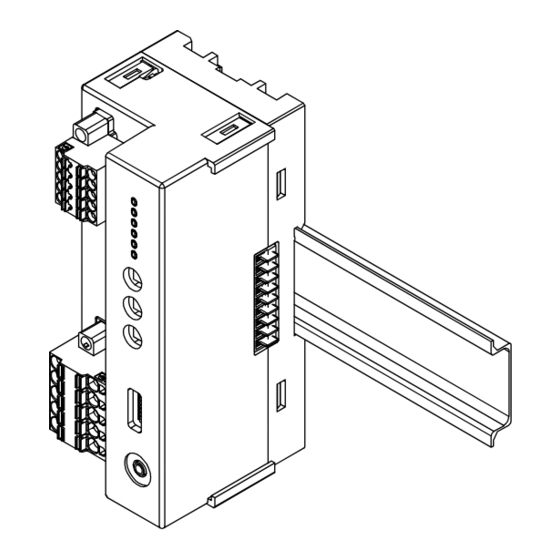
■ HOW TO MOUNT THE MODULE ON DIN RAIL
• Power/Network Module
Hang the upper hook at the rear on the DIN rail and push in the lower.
When removing the module, push down the DIN rail adaptor utilizing a
minus screwdriver and pull.
R8-NC3A
Hook
DIN Rail Adaptor
EM-9679 Rev.1 P. 1 / 10
Advertisement
Table of Contents

Related Manuals for MG R8-NC3A


Summary of Contents for MG R8-NC3A
- Page 1 • Do not install the unit where it is subjected to continuous vibration. Do not subject the unit to physical impact. EM-9679 Rev.1 P. 1 / 10 MG CO., LTD. www.mgco.jp 5-2-55 Minamitsumori, Nishinari-ku, Osaka 557-0063 JAPAN...
-
Page 2: Component Identification
1 CA = I/O module for 1 module address. Note: Be sure to set unused SW6 through 8 to OFF. Combinations of ‘–’ are invalid (Power LED blinks with 4 Hz) . EM-9679 Rev.1 P. 2 / 10 MG CO., LTD. www.mgco.jp 5-2-55 Minamitsumori, Nishinari-ku, Osaka 557-0063 JAPAN... - Page 3 *1. SD LED which is blinking may appear to be ON with high baud rate especially when fewer modules are connected. *2. LED combinations indicated with “----” do not occur in normal operation unless LED failure or the like occurs. EM-9679 Rev.1 P. 3 / 10 MG CO., LTD. www.mgco.jp 5-2-55 Minamitsumori, Nishinari-ku, Osaka 557-0063 JAPAN...
-
Page 4: Terminal Connections
■ EXTERNAL DIMENSIONS unit: mm (inch) • Unit 50 (1.97) [3 (.12)] 55 (2.17) [4 (.16)] DIN RAIL (35 mm wide) • Protective Cover 5 (.20) 50 (1.97) EM-9679 Rev.1 P. 4 / 10 MG CO., LTD. www.mgco.jp 5-2-55 Minamitsumori, Nishinari-ku, Osaka 557-0063 JAPAN... -
Page 5: Wiring Instructions
■ MASTER CONNECTION Master Station R8-NC3A R8−NC3A Blue Terminating White Resistor Yellow *1. Turn on the terminator DIP switch to activate the internal terminating resistor EM-9679 Rev.1 P. 5 / 10 MG CO., LTD. www.mgco.jp 5-2-55 Minamitsumori, Nishinari-ku, Osaka 557-0063 JAPAN... - Page 6 RX (n+26) F RY (n+26) F RWr (n+63) RWw (n+63) System area RX (n+17) 0 - F RY (n+17) 0 - F – – EM-9679 Rev.1 P. 6 / 10 MG CO., LTD. www.mgco.jp 5-2-55 Minamitsumori, Nishinari-ku, Osaka 557-0063 JAPAN...
- Page 7 (Module state: 0= Mounted, 1= Unmounted) [System area] [System area] RX (n+m) B Remote Ready Flag Unused (After reboot and preparation completion, it turns to 1.) EM-9679 Rev.1 P. 7 / 10 MG CO., LTD. www.mgco.jp 5-2-55 Minamitsumori, Nishinari-ku, Osaka 557-0063 JAPAN...
- Page 8 (Module state: 0= Mounted, 1= Unmounted) [System area] [System area] Unused RX (n+m) B Remote Ready Flag (After reboot and preparation completion, it turns to 1.) EM-9679 Rev.1 P. 8 / 10 MG CO., LTD. www.mgco.jp 5-2-55 Minamitsumori, Nishinari-ku, Osaka 557-0063 JAPAN...
- Page 9 A range, the data is 52035 as the conversion data is the engineering value multiplied by 100. Negative value is not available, the data is shown with the range 0 to 65535. EM-9679 Rev.1 P. 9 / 10 MG CO., LTD. www.mgco.jp 5-2-55 Minamitsumori, Nishinari-ku, Osaka 557-0063 JAPAN...
- Page 10 Input 2 Individual interlock 1 Input 3 Individual interlock 2 R8-DCM16ALH Input 1 Full interlock Input 2 Partial interlock 1 Input 3 Partial interlock 2 EM-9679 Rev.1 P. 10 / 10 MG CO., LTD. www.mgco.jp 5-2-55 Minamitsumori, Nishinari-ku, Osaka 557-0063 JAPAN...
Need help?
Do you have a question about the R8-NC3A and is the answer not in the manual?
Questions and answers