Advertisement
INSTRUCTION MANUAL
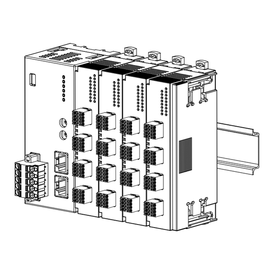
UNIVERSAL INPUT MODULE
(4 points, isolated, tension clamp terminal block)
BEFORE USE ....
Thank you for choosing us. Before use, please check con-
tents of the package you received as outlined below.
If you have any problems or questions with the product,
please contact our sales office or representatives.
■ PACKAGE INCLUDES:
Universal input module ......................................................(1)
CJC sensor ...........................................................................(4)
■ MODEL NO.
Confirm Model No. marking on the product to be exactly
what you ordered.
■ INSTRUCTION MANUAL
This manual describes necessary points of caution when
you use this product, including installation, connection and
basic maintenance procedures.
POINTS OF CAUTION
■ CONFORMITY WITH EU DIRECTIVES
• The equipment must be mounted inside a panel.
• The actual installation environments such as panel con-
figurations, connected devices, connected wires, may af-
fect the protection level of this unit when it is integrated
in a panel system. The user may have to review the CE
requirements in regard to the whole system and employ
additional protective measures to ensure the CE conform-
ity.
■ GENERAL PRECAUTIONS
• Before you remove or mount the unit, turn off the power
supply and output signal for safety.
• DO NOT set the switches while the power is supplied.
The switches are used only for maintenance without the
power.
■ ENVIRONMENT
• Indoor use.
• When heavy dust or metal particles are present in the
air, install the unit inside proper housing with sufficient
ventilation.
• Do not install the unit where it is subjected to continuous
vibration. Do not subject the unit to physical impact.
• Environmental temperature must be within -10 to +55°C
(14 to 131°F) with relative humidity within 30 to 90% RH
in order to ensure adequate life span and operation.
■ WIRING
• Do not install cables close to noise sources (relay drive
cable, high frequency line, etc.).
• Do not bind these cables together with those in which
noises are present. Do not install them in the same duct.
MG CO., LTD. www.mgco.jp
5-2-55 Minamitsumori, Nishinari-ku, Osaka 557-0063 JAPAN
MODEL
■ POWER UP
• Turn the power on at the same time as the power/network
module or turn the R80PS1 on before the power/network
module turned on. If the R80PS1 is not turned on within
3 seconds after the power/network module is turned on,
I/O modules are not correctly recognized.
R80UST4
EM-7028 Rev.2 P. 1 / 9
Advertisement
Table of Contents

Related Manuals for MG R80UST4


Summary of Contents for MG R80UST4
- Page 1 • Do not bind these cables together with those in which noises are present. Do not install them in the same duct. EM-7028 Rev.2 P. 1 / 9 MG CO., LTD. www.mgco.jp 5-2-55 Minamitsumori, Nishinari-ku, Osaka 557-0063 JAPAN...
-
Page 2: Installation
More I/O modules can be added in the same manner. When removing the cover, pull it out while squeezing the hooks inward. EM-7028 Rev.2 P. 2 / 9 MG CO., LTD. www.mgco.jp 5-2-55 Minamitsumori, Nishinari-ku, Osaka 557-0063 JAPAN... - Page 3 2) I/O modules cannot hold tightly on the DIN rail by themselves without power/network module. Secure them to the position if necessary by using DIN rail end plates. EM-7028 Rev.2 P. 3 / 9 MG CO., LTD. www.mgco.jp 5-2-55 Minamitsumori, Nishinari-ku, Osaka 557-0063 JAPAN...
-
Page 4: Component Identification
(≤ -15%, ≥ +115%, becomes less than the lower limit or exceeds the upper limit of usable range). Input circuit abnormality (AD converter response failure) EM-7028 Rev.2 P. 4 / 9 MG CO., LTD. www.mgco.jp 5-2-55 Minamitsumori, Nishinari-ku, Osaka 557-0063 JAPAN... - Page 5 – Input S – – – RTD-B RTD-B Input L Common Common Common Thermocouple- RTD-A RTD-A Input H – – – – – – EM-7028 Rev.2 P. 5 / 9 MG CO., LTD. www.mgco.jp 5-2-55 Minamitsumori, Nishinari-ku, Osaka 557-0063 JAPAN...
-
Page 6: Setting Range
*1. For details, refer to the users manual of R80CFG ■ CHANNEL BATCH SETTING ITEM SETTING RANGE DEFAULT VALUE Version no. – – Simulate input Normal input Normal input Simulated data EM-7028 Rev.2 P. 6 / 9 MG CO., LTD. www.mgco.jp 5-2-55 Minamitsumori, Nishinari-ku, Osaka 557-0063 JAPAN... -
Page 7: Terminal Connections
For thermocouple input, attach the CJC sensor together with input wining to the input screw terminals. ■ EXTERNAL DIMENSIONS unit : mm (inch) 24 [.94] (3 [.12]) 67 [2.64] (4 [.16]) 55 [2.17] DIN rail (35mm wide) EM-7028 Rev.2 P. 7 / 9 MG CO., LTD. www.mgco.jp 5-2-55 Minamitsumori, Nishinari-ku, Osaka 557-0063 JAPAN... - Page 8 R80UST4 ■ CONNECTION DIAGRAM INTERNAL BUS INTERNAL POWER Universal input 1 Universal input 2 Universal input 3 Universal input 4 EM-7028 Rev.2 P. 8 / 9 MG CO., LTD. www.mgco.jp 5-2-55 Minamitsumori, Nishinari-ku, Osaka 557-0063 JAPAN...
-
Page 9: Wiring Instructions
Note: If the stripped length does not match the length of recommended solderless terminal, adjust to the stripped length of 7mm by cutting the terminal if it is too long, or by extending the wire if the terminal is too short. EM-7028 Rev.2 P. 9 / 9 MG CO., LTD. www.mgco.jp 5-2-55 Minamitsumori, Nishinari-ku, Osaka 557-0063 JAPAN...
Need help?
Do you have a question about the R80UST4 and is the answer not in the manual?
Questions and answers