Advertisement
Quick Links
INSTRUCTION MANUAL
NETWORK MODULE
(CC-Link IE TSN network)
BEFORE USE ....
Thank you for choosing us. Before use, please check con-
tents of the package you received as outlined below.
If you have any problems or questions with the product,
please contact our sales office or representatives.
■ PACKAGE INCLUDES:
Network module ..................................................................(1)
■ MODEL NO.
Confirm Model No. marking on the product to be exactly
what you ordered.
■ INSTRUCTION MANUAL
This manual describes necessary points of caution when
you use this product, including installation, connection and
basic maintenance procedures.
■ CSP+ file
CSP+ file is downloadable at our web site or CC-Link Part-
ner Association's web site (https://.cc-link.org).
MG CO., LTD. www.mgco.jp
5-2-55 Minamitsumori, Nishinari-ku, Osaka 557-0063 JAPAN
MODEL
POINTS OF CAUTION
■ CONFORMITY WITH EU DIRECTIVES
• The equipment must be mounted inside the instrument
panel of a metal enclosure.
• The actual installation environments such as panel con-
figurations, connected devices, connected wires, may af-
fect the protection level of this unit when it is integrated
in a panel system. The user may have to review the CE
requirements in regard to the whole system and employ
additional protective measures to ensure the CE conform-
ity.
■ HOT SWAPPABLE MODULES
• It is possible to replace a module with the power supplied
provided that the module is replaced with one with the
same model number and installed in the same base slot.
• Be sure to replace a module when it is not communicating
with the host as it may affect the system. Note that re-
placing multiple modules at one time may greatly change
line voltage levels. We strongly recommend to replace
them one by one.
■ ENVIRONMENT
• Indoor use.
• When heavy dust or metal particles are present in the
air, install the unit inside proper housing with sufficient
ventilation.
• Do not install the unit where it is subjected to continuous
vibration. Do not subject the unit to physical impact.
• Environmental temperature must be within -10 to +55°C
(14 to 131°F) with relative humidity within 10 to 90% RH
in order to ensure adequate life span and operation.
■ WIRING
• Do not install cables close to noise sources (relay drive
cable, high frequency line, etc.).
• Do not bind these cables together with those in which
noises are present. Do not install them in the same duct.
■ R3 I/O MODULE EXTENSION
• The internal bus communication period for R3 series I/O
modules installed on the R30EBS is as follows.
Internal bus communication period = 6 msec. x number of
I/O module + 10 msec. (Data update period of main CPU)
Example: Four R3 I/O modules
6 msec. x 4 + 10 msec. = 34 msec.
Even when the R30EBS is mounted to the R30BS, the
internal bus communication period of R30 series is kept
to approx. 1 msec.
■ AND ....
• The unit is designed to function as soon as power is sup-
plied, however, a warm up for 10 minutes is required for
satisfying complete performance described in the data
sheet.
R30NCIT1
EM-8902 Rev.4 P. 1 / 17
Advertisement

Related Manuals for MG R30NCIT1


Summary of Contents for MG R30NCIT1
- Page 1 • The unit is designed to function as soon as power is sup- plied, however, a warm up for 10 minutes is required for satisfying complete performance described in the data sheet. EM-8902 Rev.4 P. 1 / 17 MG CO., LTD. www.mgco.jp 5-2-55 Minamitsumori, Nishinari-ku, Osaka 557-0063 JAPAN...
-
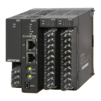
Page 2: Component Identification
*2. Host communication error, internal bus communication error etc. *3. Non-volatile memory error, or IP address / station No. setting rotary switch has been changed after turning on the module. EM-8902 Rev.4 P. 2 / 17 MG CO., LTD. www.mgco.jp 5-2-55 Minamitsumori, Nishinari-ku, Osaka 557-0063 JAPAN... - Page 3 IP address / Station No. setting rotary SW are set with hexadecimal. For example, in the case of setting station No. 175, Set the Station MSB: A and LSB: F. EM-8902 Rev.4 P. 3 / 17 MG CO., LTD. www.mgco.jp 5-2-55 Minamitsumori, Nishinari-ku, Osaka 557-0063 JAPAN...
-
Page 4: Installation
Positioning Guide Lock Tab 3) Tighten the base fixing screw using a screwdriver (stem length: 70 mm/2.76” or more) (torque 0.5 N·m). Base Fixing Screw EM-8902 Rev.4 P. 4 / 17 MG CO., LTD. www.mgco.jp 5-2-55 Minamitsumori, Nishinari-ku, Osaka 557-0063 JAPAN... -
Page 5: Terminal Connections
USB CONNECTOR CONNECTOR INTERNAL POWER Regarding CN1 and CN2 of RJ-45 connector for CC-Link IE TSN network, there is no restriction for connection order. EM-8902 Rev.4 P. 5 / 17 MG CO., LTD. www.mgco.jp 5-2-55 Minamitsumori, Nishinari-ku, Osaka 557-0063 JAPAN... - Page 6 Di16 points Slot 3 R3-DA32A Di16 points Di16 points Di16 points Slot 4 R3-DC32A Do16 points Slot 4 R3-DC32A Do16 points Do16 points Do16 points EM-8902 Rev.4 P. 6 / 17 MG CO., LTD. www.mgco.jp 5-2-55 Minamitsumori, Nishinari-ku, Osaka 557-0063 JAPAN...
- Page 7 RX(n+2)2, RX(n+4)2, RX(n+6)2 R3 series extension slot 3 RX(n+2)F, RX(n+4)F, RX(n+6)F R3 series extension slot 16 Link devices other than the above are not in use. EM-8902 Rev.4 P. 7 / 17 MG CO., LTD. www.mgco.jp 5-2-55 Minamitsumori, Nishinari-ku, Osaka 557-0063 JAPAN...
- Page 8 32-bit binary data is used for BCD. Lower 16 bits are allocated from the lowest address to higher ones, higher 16 bits in turn. Lower 16 bits Higher 16 bits EM-8902 Rev.4 P. 8 / 17 MG CO., LTD. www.mgco.jp 5-2-55 Minamitsumori, Nishinari-ku, Osaka 557-0063 JAPAN...
- Page 9 ■ DISCRETE DATA (models: R30XN16A, R30YN16x, etc.) Input 1 (Output 1) Input 2 (Output 2) Input 3 (Output 3) Input 16 (Output 16) 0 : OFF 1 : ON EM-8902 Rev.4 P. 9 / 17 MG CO., LTD. www.mgco.jp 5-2-55 Minamitsumori, Nishinari-ku, Osaka 557-0063 JAPAN...
- Page 10 R30NCIT1 SETTING ■ SUMMARY Follow the setting procedure below for configuring R30NCIT1 by using GX Works3 of Mitsubishi Electric (hereinafter referred to as GX Works3). ■ REGISTRATION FOR PROFILE This unit supports CC-Link Family system profile (CSP+). CSP+ can be downloaded from the our web site or CC-Link Partner Association’s web site (https://www.cc-link.org).
- Page 11 GX Works3 (R30NCIT1) 1) Master station, Local Station and Remote Station (R30NCIT1) are connected by Ethernet cable. CN1 and CN2 of CC-Link IE TSN Network RJ-45 modular jacks can be connected in any order. Before wiring, make sure to turn off the power of each unit.
- Page 12 4) In the following window, when [Module Label: Not use] is displayed in Module Setting, click [Setting Change] to open the option window, and change to [Use]. Click Select [Yes] for [Use Module Label] in [Operation Setting], and click [OK]. Click EM-8902 Rev.4 P. 12 / 17 MG CO., LTD. www.mgco.jp 5-2-55 Minamitsumori, Nishinari-ku, Osaka 557-0063 JAPAN...
- Page 13 PLC configuration, select the module from [POU List] of the [Element Selection] window, and drag and drop it to the module configuration diagram. Drag & Drop 6) Double click [CC-Link IE TSN network module] to open the parameter setting window. EM-8902 Rev.4 P. 13 / 17 MG CO., LTD. www.mgco.jp 5-2-55 Minamitsumori, Nishinari-ku, Osaka 557-0063 JAPAN...
- Page 14 7) Set Station Type to [Master Station], Network No. to 1 in [Required Settings]. 8) Click <Detailed Setting> of [Network Configuration Settings] in [Basic Settings] to display the [CC IE TSN Configuration] window EM-8902 Rev.4 P. 14 / 17 MG CO., LTD. www.mgco.jp 5-2-55 Minamitsumori, Nishinari-ku, Osaka 557-0063 JAPAN...
- Page 15 * When CSP+ not registered, select [General CC IE TSN Module]. Click Drag & Drop 9) Click <Detailed Setting> of [Refresh Setting] to display the Refresh Setting window EM-8902 Rev.4 P. 15 / 17 MG CO., LTD. www.mgco.jp 5-2-55 Minamitsumori, Nishinari-ku, Osaka 557-0063 JAPAN...
- Page 16 Assign link devices RX/RY/RWr/RWw to devices of the CPU unit, click [Apply] to close the window. Click 10) Click [Convert] ➞ [Convert] to execute conversion. Select EM-8902 Rev.4 P. 16 / 17 MG CO., LTD. www.mgco.jp 5-2-55 Minamitsumori, Nishinari-ku, Osaka 557-0063 JAPAN...
- Page 17 11) Click [Write to PLC...] in [Online] on menu bar to open [Online Data Operation] window. Select Check necessary items, and click [Execute]. Click EM-8902 Rev.4 P. 17 / 17 MG CO., LTD. www.mgco.jp 5-2-55 Minamitsumori, Nishinari-ku, Osaka 557-0063 JAPAN...
Need help?
Do you have a question about the R30NCIT1 and is the answer not in the manual?
Questions and answers