Table of Contents
Advertisement
Available languages
Available languages
Quick Links
Advertisement
Chapters
Table of Contents

Related Manuals for Helios SA-5 10

Summary of Contents for Helios SA-5 10
- Page 1 SA-5 10 Helios Ventilatoren 5-Stufenschalter Montage- und Betriebsvorschrift Aufbewahren zum Nachschlagen! Available on www. HeliosSelect.de Disponsible sur www. HeliosSelect.de L-BAL-E328-D 2023/33 Index 002 Art.-Nr.
-
Page 2: Table Of Contents
Montage- und Betriebsvorschrift SA-5 10 Inhaltsübersicht 1 Allgemeine Hinweise ........ -
Page 3: Allgemeine Hinweise
Montage- und Betriebsvorschrift SA-5 10 Allgemeine Hinweise 1 Allgemeine Hinweise Die Einhaltung der nachfolgenden Vorgaben dient auch der Si- cherheit des Produktes. Sollten die angegebenen Hinweise insbe- sondere zur generellen Sicherheit, Transport, Lagerung, Montage, Betriebsbedingungen, Inbetriebnahme, Instandhaltung, Wartung, Reinigung und Entsorgung / Recycling nicht beachtet werden, kann das Produkt eventuell nicht sicher betrieben werden und kann eine Gefahr für Leib und Leben der Benutzer und dritter... -
Page 4: Sicherheitshinweise
Montage- und Betriebsvorschrift SA-5 10 Sicherheitshinweise Wir haften nicht für Schäden aufgrund von Fehlgebrauch, sach- widriger Verwendung, unsachgemäßer Verwendung oder als Folge von nicht autorisierten Reparaturen bzw. Veränderungen. 2 Sicherheitshinweise Montage, elektrischer Anschluss und Inbetriebnahme dürfen • nur von einer Elektrofachkraft, entsprechend den elektrotechni- schen Regeln (u. -
Page 5: Produktübersicht
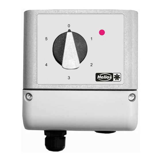
3.1 Funktion 5-Stufenschalter zur Ansteuerung von Drehzahlstellern und EC- Ventilatoren. Die Verwendung ist nur für Produkte zulässig, die von Helios dafür zugeordnet sind. Die aktuelle Zuordnung finden Sie unter www.HeliosSelect.de. Der Schalter wird mit einer 10 V DC Spannung versorgt und gibt abhängig von der Schalterstellung eine Steuerspannung aus. -
Page 6: Lagerung
Montage- und Betriebsvorschrift SA-5 10 Montage 3.2 Lagerung Das Gerät muss trocken und wettergeschützt in Originalverpa- • ckung gelagert werden. Vermeiden Sie extreme Hitze- oder Kälteeinwirkung. • Vermeiden Sie zu lange Lagerzeiten (wir empfehlen max. ein • Jahr). 3.3 Entsorgung / Recycling Die Entsorgung muss sachgerecht und umweltschonend, nach den gesetzlichen Bestimmungen des jeweiligen Landes erfolgen. - Page 7 Montage- und Betriebsvorschrift SA-5 10 Montage Das Gerät ist für eine vertikale Montage bestimmt (Kabelein- • führung unten). Eine waagrechte, bzw. liegende Montage ist nur nach technischer Freigabe des Herstellers zulässig! Nehmen Sie den Anschlussdeckel für Montage und Anschluss •...
-
Page 8: Elektrische Installation
Montage- und Betriebsvorschrift SA-5 10 Elektrische Installation 5 Elektrische Installation 5.1 EMV-gerechte Installation der Steuerleitungen Um Einstreuungen zu vermeiden, muss auf ausreichenden Ab- stand zu Netz- und Motorleitungen geachtet werden. Bei Verwendung einer geschirmten Leitung muss der Schirm ein- seitig am Signaleingang (des Auswertegerätes) mit dem Schutz- leiter verbunden werden (so kurz und induktionsarm wie möglich!). - Page 9 Montage- und Betriebsvorschrift SA-5 10 Elektrische Installation Im Auslieferungszustand sind den wählbaren Stufen folgende Ausgangsspannungen zugeordnet: Stufe 0 = 0 V Stufe 1 = 2 V Stufe 2 = 4 V Stufe 3 = 6 V Stufe 4 = 8 V Stufe 5 = 10 V Potenziometer "Offset"...
- Page 10 Montage- und Betriebsvorschrift SA-5 10 Elektrische Installation Beispiel: Stufen und mögliche Ausgangsspannungen A: Offset = 100 % B: Offset = 90 %, J1 = Offset C: Offset = 75 %, J1 = 10 V 04.02.2016 v_u_out_S-5EC.vsd L-BAL-E328-D 2023/33 Index 002 Art.-Nr.
-
Page 11: Ansteuerung Der Led
Montage- und Betriebsvorschrift SA-5 10 Elektrische Installation 5.4 Ansteuerung der LED Mit internem Stecker "J2 LED" kann gewählt werden, ob die LED den Betrieb des 5-Stufenschalters meldet oder ob diese über einen externen Kontakt angesteuert wird. Stecker "J2 LED" LED Betriebsmeldung 5-Stufenschalter Stecker "J2"... -
Page 12: Anhang
Montage- und Betriebsvorschrift SA-5 10 Anhang 6 Anhang 6.1 Technische Daten SA-5 10 Art.-Nr. 40229-001 Spannungsversorgung 10 V DC (+10 %) Max. Stromaufnahme ca. 7,5 mA Max. Belastung Ausgang 0...10 V 0,1 mA Gehäuse PC (Polycarbonat) Brandschutzklasse UL94V0 Gebrauchslage senkrecht... -
Page 13: Anschlussplan
Montage- und Betriebsvorschrift SA-5 10 Anhang 6.2 Anschlussplan SA-5 10 Step 5 Offset Offset 10V GND A LED GND 75 % 100 Ausgangspannung Output voltage Tension de sortie (0, 2, 4, 6, 8, 10 V) Externe Ansteuerung LED External control LED LED de contrôle externe... -
Page 14: Service Und Information
Montage- und Betriebsvorschrift SA-5 10 Anhang 6.4 Service und Information Helios Ventilatoren GmbH + Co KG • Lupfenstraße 8 • 78056 Villingen-Schwenningen Helios Ventilateurs • Le Carré des Aviateurs • 157 av. Charles Floquet • 93155 Le Blanc Mesnil Cedex Helios Ventilatoren AG •... - Page 15 SA-5 10 Helios fans 5-step switch Installation and Operating Specification Keep for reference! L-BAL-E328-GB 2023/33 Index 002 Part.-No.
- Page 16 Installation and Operating Specification SA-5 10 Content 1 General notes .........
-
Page 17: General Notes
Installation and Operating Specification SA-5 10 General notes 1 General notes Compliance with the following instructions is mandatory to ensure the functionality and safety of the product. If the following instruc- tions given especially but not limited for general safety, transport,... -
Page 18: Safety Instructions
Installation and Operating Specification SA-5 10 Safety instructions 2 Safety instructions Mounting, electrical connection, and start-up operation may only • be carried out by an electrical specialist in accordance with electrotechnical regulations (e.g. DIN EN 50110 or DIN EN 60204)! Persons entrusted with the planning, installation, commissioning •... -
Page 19: Product Overview
3 Product overview 3.1 Function 5-step switch for controlling speed controllers and EC fans. The use is only permitted for products that are assigned by Helios for this purpose. The current assignment can be found under www.HeliosSelect.de. The switch is supplied with a voltage of 10 V DC giving a control voltage output dependent on the switch position. -
Page 20: Storage
Installation and Operating Specification SA-5 10 Mounting 3.2 Storage The device must be stored in its original packaging in a dry and • weather-proof room. Avoid exposure to extreme heat and cold. • Avoid over-long storage periods (we recommend a maximum of •... - Page 21 Installation and Operating Specification SA-5 10 Mounting The device is designed for vertical installation (bottom cable • inlet). A horizontal or reclined installation is only permissible after technical release of the manufacturer! Remove the connection cover for mounting and connection, and •...
-
Page 22: Electrical Installation
Installation and Operating Specification SA-5 10 Electrical installation 5 Electrical installation 5.1 EMC-compatible installation of control lines Pay attention to maintain sufficient distance from powerlines and motor wires to prevent interferences. When using a shielded cable the shield must be connected (as short and with as low an induction as possible!) to the PE conduc- tor on one side at the signal input (of the evaluation unit). - Page 23 Installation and Operating Specification SA-5 10 Electrical installation Step 0 = 0 V Step 1 = 2 V Step 2 = 4 V Step 3 = 6 V Step 4 = 8 V Step 5 = 10 V Potentiometer "Offset"...
- Page 24 Installation and Operating Specification SA-5 10 Electrical installation Example: Steps and possible output voltages A: Offset = 100 % B: Offset = 90 %, J1 = Offset C: Offset = 75 %, J1 = 10 V 04.02.2016 v_u_out_S-5EC.vsd L-BAL-E328-GB 2023/33 Index 002 Part.-No.
-
Page 25: Led Control
Installation and Operating Specification SA-5 10 Electrical installation 5.4 LED control With internal jumper "J2 LED" it can be selected whether the LED registers the operation of the 5-step switch or if it is controlled via an external contact. Jumper "J2 LED"... -
Page 26: Enclosure
Installation and Operating Specification SA-5 10 Enclosure 6 Enclosure 6.1 Technical data Type SA-5 10 Part-No. 40229-001 Voltage supply 10 V DC (+10 %) Max. current consumption ca. 7.5 mA Max. load output 0...10 V 0.1 mA Housing PC (polycarbonate) Fire protection classification UL94V0... -
Page 27: Connection Diagram
Installation and Operating Specification SA-5 10 Enclosure 6.2 Connection diagram SA-5 10 Step 5 Offset Offset 10V GND A LED GND 75 % 100 Ausgangspannung Output voltage Tension de sortie (0, 2, 4, 6, 8, 10 V) Externe Ansteuerung LED External control LED LED de contrôle externe... -
Page 28: Service And Information
Installation and Operating Specification SA-5 10 Enclosure 6.4 Service and Information Helios Ventilatoren GmbH + Co KG • Lupfenstraße 8 • 78056 Villingen-Schwenningen Helios Ventilateurs • Le Carré des Aviateurs • 157 av. Charles Floquet • 93155 Le Blanc Mesnil Cedex Helios Ventilatoren AG •... - Page 29 SA-5 10 Ventilateurs Helios Commutateur à 5 niveaux Prescription de montage et d’utilisation À conserver pour consultation ultérieure ! L-BAL-E328-F 2023/33 Index 002 Art.N°.
- Page 30 Prescription de montage et d’utilisation SA-5 10 Sommaire 1 Instructions générales ....... . .
-
Page 31: Instructions Générales
Prescription de montage et d’utilisation SA-5 10 Instructions générales 1 Instructions générales Le respect des consignes suivantes vise également à assurer la sécurité du produit. Si les consignes de sécurité en général, de transport, de stockage, de montage, d'utilisation, de mise en ser- vice, de maintenance, d'entretien, de nettoyage et d'élimination/re-... -
Page 32: Consignes De Sécurité
Prescription de montage et d’utilisation SA-5 10 Consignes de sécurité utilisation non pertinente ou de réparations ou modifications non autorisées. 2 Consignes de sécurité Le montage, le raccordement électrique et la mise en service ne • doivent être effectués que par un électricien dans le respect des règlements électrotechniques (entre autres DIN EN 50110 ou... -
Page 33: Aperçu Des Produits
Commutateur à 5 niveaux pour la commande de variateurs de vitesse et de ventilateurs EC. L'utilisation est autorisée uniquement pour les produits sélection- nés par Helios. Vous trouverez la sélection actuelle sous www.He- liosSelect.de. Le commutateur est alimenté par une tension de 10 V DC et délivre une tension de commande en fonction de la position du... -
Page 34: Stockage
Prescription de montage et d’utilisation SA-5 10 Montage 3.2 Stockage L'appareil doit être stocké au sec et à l’abri des intempéries • dans son emballage d’origine. Evitez des températures extrêmes vers le haut ou vers le bas. • Evitez de l’entreposer trop longtemps (nous recommandons un •... - Page 35 Prescription de montage et d’utilisation SA-5 10 Montage L’appareil est prévu pour être monté verticalement (introduction • du câble par le bas). Un montage horizontal ou couché n’est autorisé qu’après accord du technique fabricant ! Retirez le couvercle de raccordement pour le montage et le •...
-
Page 36: Installation Électrique
Prescription de montage et d’utilisation SA-5 10 Installation électrique 5 Installation électrique 5.1 Installation conforme CEM des câbles de commande Pour éviter les interférences, respecter une distance suffisante par rapport aux câbles de réseau et aux câbles moteur. En cas d’utilisation d’un câble blindé, le blindage doit être relié... - Page 37 Prescription de montage et d’utilisation SA-5 10 Installation électrique À l'état de livraison, les tensions de sortie suivantes sont affectées aux niveaux sélectionnables : Niveau 0 = 0 V Niveau 1 = 2 V Niveau 2 = 4 V Niveau 3 = 6 V...
- Page 38 Prescription de montage et d’utilisation SA-5 10 Installation électrique Exemple : niveaux et tensions de sortie possibles A: Offset = 100 % B: Offset = 90 %, J1 = Offset C: Offset = 75 %, J1 = 10 V 04.02.2016 v_u_out_S-5EC.vsd...
-
Page 39: Commande De La Led
Prescription de montage et d’utilisation SA-5 10 Installation électrique 5.4 Commande de la LED Le connecteur interne "J2 LED" permet de choisir si la LED signale le fonctionnement du commutateur à 5 niveaux ou si celle- ci est commandée par un contact externe. -
Page 40: Annexe
Prescription de montage et d’utilisation SA-5 10 Annexe 6 Annexe 6.1 Caractéristiques techniques Type SA-5 10 Art.N°. 40229-001 Alimentation en tension 10 V DC (+10 %) Consommation de courant max. env. 7,5 mA Charge max. sortie 0...10 V 0,1 mA Boîtier... -
Page 41: Schéma De Raccordement
Prescription de montage et d’utilisation SA-5 10 Annexe 6.2 Schéma de raccordement SA-5 10 Step 5 Offset Offset 10V GND A LED GND 75 % 100 Ausgangspannung Output voltage Tension de sortie (0, 2, 4, 6, 8, 10 V) Externe Ansteuerung LED External control LED LED de contrôle externe... -
Page 42: Service Et Information
Prescription de montage et d’utilisation SA-5 10 Annexe 6.4 Service et information Helios Ventilatoren GmbH + Co KG • Lupfenstraße 8 • 78056 Villingen-Schwenningen Helios Ventilateurs • Le Carré des Aviateurs • 157 av. Charles Floquet • 93155 Le Blanc Mesnil Cedex Helios Ventilatoren AG •...
Need help?
Do you have a question about the SA-5 10 and is the answer not in the manual?
Questions and answers