Table of Contents
Advertisement
Quick Links
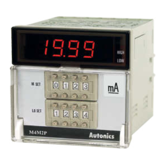
TCD210079AA
Indicator / Thumbwheel
Switch Panel Meters
M4M Series
PRODUCT MANUAL
For your safety, read and follow the considerations written in the instruction
manual, other manuals and Autonics website.
The speci昀椀cations, dimensions, etc. are subject to change without notice for product
improvement. Some models may be discontinued without notice.
Features
• Max. display value: 1999
• Auto-zero function and hold display value function
• Linear display based on input speci昀椀cation
• Display output values (0 - 10 VDCᜡ) from power converters
(options available for DC 4 - 20 mA, 1 - 5 VDCᜡ)
• RMS or AVG value selection (AC voltage)
• 7-segment LED display
• DIN standard size models
ᜫ
Safety Considerations
• Observe all 'Safety Considerations' for safe and proper operation to avoid hazards.
• symbol indicates caution due to special circumstances in which hazards may occur.
Warning
Failure to follow instructions may result in serious injury or death.
01. Fail-safe device must be installed when using the unit with machinery that
may cause serious injury or substantial economic loss. (e.g. nuclear power
control, medical equipment, ships, vehicles, railways, aircraft, combustion
apparatus, safety equipment, crime / disaster prevention devices, etc.)
Failure to follow this instruction may result in personal injury, economic loss or 昀椀re.
02. Do not use the unit in the place where 昀氀ammable / explosive / corrosive gas,
high humidity, direct sunlight, radiant heat, vibration, impact or salinity
may be present.
Failure to follow this instruction may result in explosion or 昀椀re.
03. Install on a device panel to use.
Failure to follow this instruction may result in 昀椀re or electric shock.
04. Do not connect, repair, or inspect the unit while connected to a power source.
Failure to follow this instruction may result in 昀椀re or electric shock.
05. Check 'Connections' before wiring.
Failure to follow this instruction may result in 昀椀re.
06. Do not disassemble or modify the unit.
Failure to follow this instruction may result in 昀椀re or electric shock.
Caution
Failure to follow instructions may result in injury or product damage.
01. When connecting the power / measurement input and relay output, use
AWG 24 (0.20 mm
) to AWG 15 (1.65 mm
2
terminal screw with a tightening torque of 0.98 to 1.18 N m.
Use the wiring suitable for the load current capacity.
Failure to follow this instruction may result in 昀椀re or malfunction due to contact
failure.
02. Use the unit within the rated speci昀椀cations.
Failure to follow this instruction may result in 昀椀re or product damage.
03. Use a dry cloth to clean the unit, and do not use water or organic solvent.
Failure to follow this instruction may result in 昀椀re or electric shock.
04. Keep the product away from metal chip, dust, and wire residue which 昀氀ow
into the unit.
Failure to follow this instruction may result in 昀椀re or product damage.
Cautions during Use
• Follow instructions in 'Cautions during Use' .
Otherwise, It may cause unexpected accidents.
• Install a power switch or circuit breaker in the easily accessible place for supplying or
disconnecting the power.
• Keep away from high voltage lines or power lines to prevent inductive noise.
In case installing power line and input signal line closely, use line 昀椀lter or varistor at
power line and shielded wire at input signal line.
Do not use near the equipment which generates strong magnetic force or high
frequency noise.
Connection with the line 昀椀lter
Install the line filter
close to the panel meter
Panel meter
110 / 220 VACᜠ
HI
LOW
Earth ground
• This unit may be used in the following environments.
- Indoors (in the environment condition rated in 'Speci昀椀cations')
- Altitude max. 2,000 m
- Pollution degree 2
- Installation category II
) cable or over and tighten the
2
Connection with the varistor
Panel meter
110 / 220 VACᜠ
HI
LOW
Advertisement
Table of Contents

Subscribe to Our Youtube Channel
Related Manuals for Autonics M4M Series


Summary of Contents for Autonics M4M Series
- Page 1 110 / 220 VACᜠ For your safety, read and follow the considerations written in the instruction 110 / 220 VACᜠ manual, other manuals and Autonics website. The speci昀椀cations, dimensions, etc. are subject to change without notice for product Earth ground improvement. Some models may be discontinued without notice.
- Page 2 SOURCE • Bracket × 2 • Power option Dimensions 24 - 70 VDCᜡ 100 - 240 VACᜠ • Unit: mm, For the detailed drawings, follow the Autonics website. • Following items are based on single setting model. 14.2 111.8 □72 11.7 ■ Bracket ■...
- Page 3 -|Transparent Guide|- Speci昀椀cations Connections of Applications ■ DC voltmeter connection Input type Scaling Rotation, voltage voltage speed • V1 (measuring voltage): ≤ 300 VDCᜡ • V1 (measuring voltage): ≥ 300 VDCᜡ Power current current ≤ 10 Multiplier ≤ 300 ≤ 400 ≤...
- Page 4 There are AC voltage and DC voltage for output voltage. ■ Scaling meter connection Temperature OUTPUT: Sensor CONVERTER Power Panel DC 4 - 20 mA supply meter Pressure Sensor 18, Bansong-ro 513Beon-gil, Haeundae-gu, Busan, Republic of Korea, 48002 www.autonics.com | +82-51-519-3232 | sales@autonics.com...
Need help?
Do you have a question about the M4M Series and is the answer not in the manual?
Questions and answers