Helios WHSH HE 24 V (0-10 V) M Installation And Operating Instructions Manual
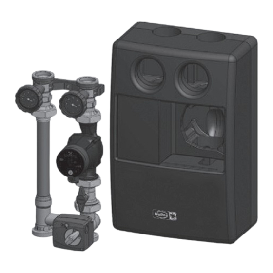
Hydraulic unit with circulating pump and 3-way valve
Hide thumbs
Also See for WHSH HE 24 V (0-10 V) M:
Table of Contents
Advertisement
Available languages
Available languages
Quick Links
Advertisement
Chapters
Table of Contents

Related Manuals for Helios WHSH HE 24 V (0-10 V) M


Summary of Contents for Helios WHSH HE 24 V (0-10 V) M
- Page 1 Helios Ventilatoren MONTAGE- UND BETRIEBSVORSCHRIFT INSTALLATION AND OPERATING INSTRUCTIONS Hydraulikeinheit Hydraulic Unit WHSH HE 24 V (0-10 V) M mit Umwälzpumpe und 3-Wege-Ventil with Circulating Pump and 3-Way Valve...
-
Page 2: Table Of Contents
Montage- und Betriebsvorschrift Hydraulikeinheit WHSH HE 24 V (0-10 V) M DEUTSCH Inhaltsverzeichnis KAPITEL 1 ALLGEMEINE MONTAGE- UND BETRIEBSHINWEISE . . . . . . . . . . . . . . . . . . . . . . . . . . . . . . . . . . Seite 1 1.0 Wichtige Informationen . -
Page 3: Wichtige Informationen
Die Betriebssicherheit ist nur bei bestimmungsgemäßer Verwendung der Hydraulikeinheit gewährleistet. Die Hydraulikbaugruppe WHSH HE 24 V (0-10 V) M wird zum Betrieb eines Heizkreislaufs in Verbindung mit einem Helios Warmwasser-Heizregister eingesetzt. Sie steuert den Durchfluss des Wassers im Heizregister. Die Vorlauftemperatur zum Heizregister wird mit Hilfe eines 3-Wege-Ventils geregelt, das durch einen elektrischen Stellmotor 24 V (0-10V) betrieben wird. -
Page 4: Garantieansprüche - Haftungsausschluss
Alle Ausführungen dieser Dokumentation müssen beachtet werden, sonst entfällt die Gewährleistung. Gleiches gilt für Haftungsansprüche an Helios. Der Gebrach von Zubehörteilen, die nicht von Helios empfohlen oder angeboten werden, ist nicht statthaft. Eventuell auftretende Schäden unterliegen nicht der Gewährleistung. Veränderungen und Umbauten am Gerät sind nicht zulässig und führen zum Verlust der Konformität, jegliche Gewährleistung und Haftung... -
Page 5: Materialien
Montage- und Betriebsvorschrift Hydraulikeinheit WHSH HE 24 V (0-10 V) M Medium: Nicht aggressive Flüssigkeiten (z.B. Wasser und geeignete Wasser-Glykolgemische gemäß VDI 2035). Nicht für Dampf, ölhaltige und aggressive Medien geeignet. 2 .1 Materialien Armaturen: Messing Pumpe: Gehäuse aus Grauguss Handgriffe: PA 6.6... -
Page 6: Einbau
Montage- und Betriebsvorschrift Hydraulikeinheit WHSH HE 24 V (0-10 V) M Montage, Erstinbetriebnahme, Wartung und Reparaturen müssen von autorisierten Fachkräften (Heizungsfachbetrieb/ Vertragsinstallationsunternehmen) durchgeführt werden. (EN 5011 Teil 1 und VDE 1000 Teil 10 für Arbeiten an elektrischen Einrichtungen) Der Vorlauf ist werksseitig rechts angeordnet. Vor- und Rücklauf können jedoch vor Ort individuell gewechselt wer- den. -
Page 7: Stellmotor
Montage- und Betriebsvorschrift Hydraulikeinheit WHSH HE 24 V (0-10 V) M Schwerkraftbremse geöffnet > Füllen, Spülen, Entlüften Durchfluss in beide Richtungen möglich. Bei Inbetriebnahme bzw. Wartungsarbeiten (Füllen und Spülen) muss die Schwerkraftbremse geöffnet sein. Im Heizbetrieb muss diese wieder in die Betriebsstellung gebracht werden. -
Page 8: Änderung Der Durchflussrichtung
Montage- und Betriebsvorschrift Hydraulikeinheit WHSH HE 24 V (0-10 V) M Abb .8 − Betriebsschalter (8) auf Handbetrieb stellen. − Drehrichtungsanzeige (5) gemäß Abbildung auf den Stellmotor (4) legen. − Handverstellgriff (7) auf die Mischerachse stecken. Der Handverstellgriff lässt sich nur in einer Rasterstellung leicht aufdrücken . Keine Gewalt anwenden! Handverstellgriff im Uhrzeigersinn bis zum Anschlag drehen. -
Page 9: Wandhalterung
BETRIEB berücksichtigen. 4 .1 Korrekturfaktoren für Wasser-Glykol-Gemische Die Korrekturfaktoren der Frostschutzmittelhersteller müssen bei der Durchflusseinstellung berücksichtigt werden. 4 .2 Wartung und Pflege Die Armatur ist wartungsfrei. 4 .3 Gewährleistung Es gelten die zum Zeitpunkt der Lieferung gültigen Gewährleistungsbedingungen von Helios. - Page 10 Installation and Operating Instructions Hydraulic Unit WHSH HE 24 V (0-10 V) M ENGLISH Table of Contents CHAPTER 1 GENERAL INSTALLATION AND OPERATING INSTRUCTIONS . . . . . . . . . . . . . . . . . . . . . . . . . . Page 1 1.0 Important information .
-
Page 11: Chapter 1 General Installation And Operating Instructions
The flow temperature to the heating register is controlled with a 3-way valve, which is operated by an electric actuator 24 V (0-10V). The hydraulic unit WHSH HE 24 V (0-10 V) M enables the time and space-saving connection of the heating register to the heating network. -
Page 12: Warranty Claims - Exclusion Of Liability
All versions of this documentation must be observed, otherwise the warranty shall cease to apply. The same applies to liability claims against Helios. The use of accessory parts, which are not recommended or offered by Helios, is not permitted. Any possible damages are not covered by the warranty. Changes and modifications to the unit are not per- mitted and lead to a loss of conformity, and any warranty and liability shall be excluded in this case. -
Page 13: Materials
Installation and Operating Instructions Hydraulic Unit WHSH HE 24 V (0-10 V) M Medium: Non-aggressive liquids (e.g. water and appropriate water glycol mixtures according to VDI 2035). Not suitable for steam, oily and aggressive media. 2 .1 Materials Fittings: Brass... -
Page 14: Installation
Installation and Operating Instructions Hydraulic Unit WHSH HE 24 V (0-10 V) M Assembly, initial commissioning, maintenance and repairs must be carried out by authorised specialists (heating contractor/contract installation company). (EN 5011 part 1 and VDE 1000 part 10 for work on electrical installations) The flow is on the right side as a standard factory setting. -
Page 15: Actuator
Installation and Operating Instructions Hydraulic Unit WHSH HE 24 V (0-10 V) M Check valve open > Filling, flushing, venting Flow possible in both directions. With regard to commissioning or maintenance work (filling and rinsing), the check valve must be open. -
Page 16: Change Of Flow Direction
Installation and Operating Instructions Hydraulic Unit WHSH HE 24 V (0-10 V) M Fig .8 Blue − Set operating switch (8) to manual operation. − Place rotation direction indicator (5) on actuator (4) pursuant to illustration. − Place adjustment handle (7) on the mixer axle. -
Page 17: Wall Bracket
The correction factors of the antifreeze agent manufacturer must be taken into account for the flow setting. 4 .2 Maintenance and care The fitting is maintenance-free. 4 .3 Warranty The applicable Helios warranty conditions at the time of delivery shall apply. - Page 18 Installation and Operating Instructions Hydraulic Unit WHSH HE 24 V (0-10 V) M...
- Page 19 Installation and Operating Instructions Hydraulic Unit WHSH HE 24 V (0-10 V) M...
- Page 20 HELIOS Ventilatoren GmbH + Co KG · Lupfenstraße 8 · 78056 VS-Schwenningen HELIOS Ventilateurs · Le Carré des Aviateurs · 157 av. Charles Floquet · 93155 Le Blanc Mesnil Cedex CH HELIOS Ventilatoren AG · Tannstraße 4 · 8112 Otelfingen GB HELIOS Ventilation Systems Ltd.
Need help?
Do you have a question about the WHSH HE 24 V (0-10 V) M and is the answer not in the manual?
Questions and answers