Uniden BCD396T Owner's Manual
Scanning radio
Hide thumbs
Also See for BCD396T:
- Owner's manual (156 pages) ,
- Owner's manual (156 pages) ,
- Manual (52 pages)
Table of Contents
Advertisement
Quick Links
Advertisement
Table of Contents

Related Manuals for Uniden BCD396T


Summary of Contents for Uniden BCD396T
- Page 1 BCD396T OWNER’S MANUAL OWNER’S MANUAL...
- Page 2 Changes or modifications to this product not expressly approved by Uniden, or operation of this product in any way other than as detailed by this Operating Guide, could void your authority to operate this product.
- Page 3 WARNING! Uniden does not represent this unit to be waterproof. To reduce the risk of fire or electrical shock, do not expose this unit to rain or moisture. ® ® Astro , DPL , Digital Private Line ® ® , PRIVACY PLUS , Private Line ®...
-
Page 4: Table Of Contents
About This Manual ... 16 Using the Multifunction Scroll Control ... 16 Entering Text ... 17 How the Scanner’s Controls Are Represented in This Manual ... 17 Understanding Scanning ... 19 Understanding the Scanner’s Memory ... 19 What is Scanning? ... 19 What is Searching? ... - Page 5 Setting the Audio AGC ... 55 Adjusting the Display Contrast ... 55 Initializing the Scanner’s Memory ... 56 Connecting Your Scanner to a Personal Computer ... 56 Using the Cloning Options ... 57 Wired Cloning ... 57 On-Air Cloning ... 58 Programming Radio Systems ...60...
- Page 6 Channel-Level Settings... 86 Editing the Channel Name... 86 Editing Frequencies (Conventional Channels Only) ... 87 Setting Channel Priority (Conventional Channels Only) ... 87 Setting Channel Alert... 88 Editing the Talk Group ID (Trunked Channels Only) ... 88 Setting CTCSS/DCS (Conventional Channels Only)... 89 Setting the System Frequency Modulation ...
- Page 7 Troubleshooting ... 121 Specifications ... 125 Optional Accessories ... 128 Appendix ... 129 Preset Fleet Maps ... 129 User Defined Fleet Maps ... 131 Type I Programming Information ... 131 Size Code Restrictions ... 132 Planning ... 133 Collecting Information ... 133 Filling Out The Conventional System Worksheet ...
-
Page 8: The Fcc Wants You To Know
If this scanner does cause harmful interference to radio or television reception, which can be determined by turning the scanner on and off, you are encouraged to try to correct the interference by one or more of the following measures: •... - Page 9 In some areas, mobile and/or portable use of this scanner is unlawful or requires a permit. Check the laws in your area. It is also illegal in many areas (and a bad idea everywhere) to interfere with the duties of public safety officials by traveling to the scene of an incident without authorization.
-
Page 10: Introduction
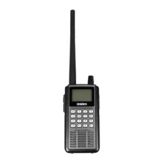
Introduction Introduction Your BCD396T scanner is a state-of-the-art scanner radio with TrunkTracker IV™ and automatic scanning capabilities. You can store frequencies such as police, fire/emergency, marine, air, amateur, and other communi- cations into the scanner. You can carry it with you wher- ever you go. -
Page 11: Feature Highlights
“Preprogrammed Sys- tems” on Page 144. 100 Quick Keys – You can set the scanner so you can quickly select systems and groups by using the keypad. This makes it easy to listen to or quickly lock out those systems or groups you don’t want to scan. - Page 12 Channel Alert – You can set the scanner so it alerts you when there is activity on any channel you specify. Memory Check – Lets you see at a glance how much total memory is left.
-
Page 13: Trunk Tracking
(5, 6.25, 7.5, 8.33, 10, 12.5,15, 20, 25, 50 or 100 kHz) for manual mode and chain search mode. The scan- ner’s auto step feature lets you set the scanner so it automatically chooses the correct step. Quick Recall – Lets you quickly select a specific channel by choosing the system, group, and channel. -
Page 14: Auto Store
This helps you quickly find out about severe weather in your area and lets you avoid false alarms. WX Priority – Lets your scanner alert you when a SAME weather priority alert is transmitted on a NOAA weather channel. -
Page 15: Pc Control And Cloning
Free PC control and programming software will be available at http://www.uniden.com. Clone Mode – You can clone all programmed data, including the contents of the scanner’s memory, menu settings, and other parameters from one BCD396T scanner to another BCD396T scanner. Feature Highlights... -
Page 16: About This Manual
On-Air Cloning – You can clone all programmed data over the air from a PC to one or more BCD396T scanners. About This Manual The screen displays used in this manual are representations of what might appear when you use your scanner. -
Page 17: How The Scanner's Controls Are Represented In This Manual
This example shows you how to use the scanner’s menu to edit an existing system name. It shows you ) to select a menu option and... - Page 18 “Understanding Scanning” on Page 19 for a quick background on the technology. The first thing you’ll need to do is install batteries in the scanner. Then you need to connect the included antenna to the scanner. See “Setting Up Your Scanner” on Page 32 if you need any help doing this.
-
Page 19: Understanding Scanning
ID’s. What is Scanning? Unlike standard AM or FM radio stations, most two- way communications do not transmit continuously. Your BCD396T scans programmed channels until it Understanding Scanning... -
Page 20: What Is Searching
What is Searching? The BCD396T can search each of its 12 bands and up to 10 bands together to find active frequencies. This is different from scanning because you are searching for frequencies that have not been programmed into the scanner. - Page 21 The stations might even interfere with each other to the point where it is impossible to clearly receive any of the stations. A scanner equipped with CTCSS and DCS (like your scanner) can code each received frequency with a specific CTCSS or DCS frequency.
-
Page 22: Conventional Scanning
When you are scanning a conventional system, the scanner stops very briefly on each channel to see if there is activity. If there isn’t, the scanner quickly moves to the next channel. If there is, then the scanner pauses on the transmission until it is over. -
Page 23: Simplex Operation
Typical repeater systems provide coverage out to about a 25-mile radius from the repeater location. What is Trunk Tracking? Your BCD396T is designed to track the following types of trunking systems. • Motorola Astro (APCO 25) trunking systems. • Motorola Type I, Type II, Type IIi hybrid,... -
Page 24: Trunked Scanning
460.500 MHz, the fire department on 154.445 MHz, the highway department on 37.900 MHz, etc. So when your scanner stops on a frequency, you usually know who it is, and more importantly, you can stop on a channel and listen to an entire conversation. -
Page 25: Types Of Trunking Systems
Uniden’s invention of the TrunkTracker scanner. Not only does your BCD396T scan channels like a conventional scanner, it actually follows the users of a trunked radio system. Once you know a talk group’s ID, you won’t miss any of the action. - Page 26 The computer then assigns that talk group to a specific voice channel and transmits that data over the control channel. All radios in that talk group switch over to the assigned voice channel and the user can begin speak- ing. This all typically takes place in about a sec- ond...the person transmitting hears a beep from their radio when the channel is assigned and then it is OK to start talking.
-
Page 27: Edacs Trunking
Also, talk groups are assigned in an Agency-Fleet-Subfleet (AFS) hierarchy. Also, there is one variation of EDACS called SCAT that your BCD396T can monitor. Logical Channel Numbers – each frequency used by the system is assigned an LCN. This information is programmed into each user radio. -
Page 28: Ltr Trunking
Autonomous Trunking) systems operate on a single channel and alternate control data with analog voice traffic. While your BCD396T cannot track ID’s in this system, it can eliminate the control data so that all you hear is the voice transmissions when you monitor this type of system. -
Page 29: I-Call (Motorola/Edacs)
I-Call (Motorola/EDACS) I-calls are direct unit-to-unit transmissions that are not heard by other system users. Your BCD396T can receive I-call transmissions. See “Setting I-Call (Motorola and EDACS Systems Only)” on Page 79 for more information about monitoring I-call transmissions. Where To Get More Information By itself, this manual only provides part of what you need to know to have fun scanning –... - Page 30 • http://groups.yahoo.com/group/BCD396T group for people interested in discussing the BCD396T. * - These web sites are not affiliated with Uniden Corporation. For more information about Uniden and our products, visit http://www.uniden.com. Understanding Scanning...
-
Page 31: Included With Your Scanner
Belt Clip BNC/SMA Adapter If any of these items are missing or damaged, immediately contact your place of purchase or Uniden Customer Service at: (800) 297-1023, 8:00 a.m. to 5:00 p.m., Central, Monday through Friday. Included With Your Scanner... -
Page 32: Setting Up Your Scanner
Owners Manual. • Do not use the scanner in high-moisture environments such as the kitchen or bathroom. • Avoid placing the scanner in direct sunlight or near heating elements or vents. Using Internal Batteries You can power your scanner using three alkaline or rechargeable AA batteries. -
Page 33: Using Rechargeable Batteries
To charge the batteries, set ALKALINE/ Ni-MH inside the battery compartment to NI-MH, install the batteries in the scanner, and connect the supplied AC adapter to the scanner's DC 6V jack (see “Using AC Power” on Page 34). WARNING! -
Page 34: Removing The Display Sticker
If an AC adapter is connected to the scanner, the scanner checks the condition of the installed batteries. If the scanner is turned off and the batteries require a full charge, Pre-Charging appears on the display. Then, Normal Charging appears as the batteries are recharged. -
Page 35: Connecting The Antenna
Connecting the Antenna To attach the supplied flexible antenna to the connector on the top of your scanner, simply screw it onto the scanner's SMA connector. Connecting an Optional Antenna The scanner's SMA connector makes it easy to connect a variety of optional antennas, including an external mobile antenna or outdoor base station antenna. -
Page 36: Attaching The Belt Clip
This might damage the scanner. Attaching the Belt Clip To make your scanner easier to carry when you are on the go, use the supplied belt clip. Rotate the scanner upside down to remove it from the clip. - Page 37 If your scanner's keys seem confusing at first, the fol- lowing information should help you understand each key's function. Key Name Description Hold – Holds the scan or the Hold/ frequency search when pressed. Resumes the scan or the frequency search when pressed again.
- Page 38 Key Name Description – Turns the display backlight on or off. Press and hold for more than 2 seconds to turn the scanner on or off. – Locks and unlocks Func the keypad. 1-9, 0 1-9, 0 – Enters a frequency, enters...
-
Page 39: A Look At The Display
(for conventional systems) or system (for trunked systems). A Look At The Display The display has indicators that show the scanner's current operating status. The display information helps you understand how your scanner operates. Sn: - appears with a number to show the currently- selected System Quick Key number. - Page 40 - appears when you hold down function. - appears when the scanner is set to a Close Call feature mode (see “Using the Close Call Feature” on Page 103). SCAN - scrolls while the scanner is scanning.
-
Page 41: Using Menu
Using Menu Func Menu Press on the left side of the scanner to enter the Menu menu. See “Using the Menu” on Page 49 for more information about the scanner’s menu options. Using Func... -
Page 42: Basic Operation
Basic Operation Basic Operation Turning On the Scanner and Setting the Squelch Note: Make sure the scanner's antenna is connected before you turn it on. 1. Press and hold for about 2 seconds to turn on the scanner. 2. Briefly press the scroll control once. -
Page 43: Scanning Systems
• The BCD396T scans a system for the duration you set using the System Hold Time option (see “Setting the System Hold Time” on Page 76). For... -
Page 44: Selecting Systems To Scan
You can scan the preprogrammed systems more efficiently by preventing the BCD396T from trying to scan systems that are not in your area. To do this, refer to the quick key assignments listed in “Preprogrammed Systems”... -
Page 45: Selecting System Channel Groups
To select or lock out a system that is not assigned to a key, press and hold while you rotate the scroll Func control until the desired system is selected. Then, continue to hold and press L/O to either lock out Func or unlock the system. -
Page 46: Id Scan/Id Search Mode
While you are scanning a trunked system, the scanner can be in either ID Scan or ID Search mode: • ID Scan – the scanner only stops on talk group ID’s that you have programmed into the system • ID Search – the scanner stops on any unlocked talk group that becomes active. -
Page 47: Quickly Storing An Id During Id Search
Then, the scanner prompts you to save other channel settings. If you enter a talk group ID then press E, the scanner stores it into a channel group named Qck Save Grp in the current system. If the talk group ID’s format is... -
Page 48: Quickly Recalling Channels
For Motorola systems, the scanner will show the System ID on the top line of the display. For EDACS systems, the scanner will show the site ID on the top line of the display. Toggling Channel Alpha Tags... -
Page 49: Using The Menu
Using the Menu Using the Menu The scanner’s menu lets you select options that let you set up and use the scanner. To use the menu, press on the left side of the Menu scanner. To select a menu item, rotate the scroll control clockwise or counterclockwise. - Page 50 -- M E N U -- Set Backlight Tone-Out for ... Adjust Key Beep Xfer Information Set Battery Save Srch/CloCall Opt Settings Set Audio AGC Adjust Contrast PC Control See Scanner Info (104) (104) (104) (104) (104) (104) (54) (54) (54) (54)
-
Page 51: Programming Systems Menu
Programming Systems Menu This table shows the scanner’s systems menu structure. This menu lets you program new systems or change existing systems. To find information about a particular menu setting in this manual, go to the page number shown under or next to the setting. - Page 52 Menu/ Option Menu Submenu Select Sys Type System 1 Conventional Edit Name Edit Sys Option Set Frequencies EDCS Srch/CloCall Op Srch/CloCall Opt Set Modulation Set Attenuator “Programming LTR Systems” on Edit Group Page 70 Delete System Copy System (74) (75) (71) (65) (83)
-
Page 53: Other Settings
Auto - the scanner automatically sets the key beep to match the master volume setting level you select. Level 1 - 15 the scanner lets you select a key beep level. You can choose any of 15 different key beep levels. -
Page 54: Turning Power Save On Or Off
Turning Power Save On or Off Settings Menu Set Battery Save • On The scanner goes into low-power mode when you monitor a conventional channel that has no activity. • Off Power save is off. Priority Scan Set Priority Menu... -
Page 55: Setting The Audio Agc
• Off Press the scroll control to select. Audio AGC is turned off. Adjusting the Display Contrast Settings Menu Adjust Contrast Contrast 1 - 15 the scanner adjusts the display to the contrast level you select. again. Set Audio AGC Other Settings... -
Page 56: Initializing The Scanner's Memory
To initialize the scanner’s memory, turn off the scanner. Then, press 2, 9, and Hold while turning it on. You can retore factory programmed data when you next see: Restore Preprogram List? Press “E yes” for Yes or “.”... -
Page 57: Using The Cloning Options
Use the included connection cable to connect your scanner to another BCD396T scanner or your per- sonal computer. Settings Menu PC Control PC Control Lets you set the baud rate your scanner uses to communicate with a personal computer. • Off The baud rate is not set. -
Page 58: On-Air Cloning
If the transfer did not work, Error appears on the master scanner. On-Air Cloning You can clone (copy) data from a PC to a BCD396T scanner. This is useful if you want to quickly program 20 or more BCD396T scanners at the same time. - Page 59 When you are receiving the cloning broadcast and are ready to clone the scanner, select Start Cloning on the scanner. The scanner receives the data from the transmission When the transfer is complete, Complete appears.
-
Page 60: Programming Radio Systems
Programming Radio Systems Programming Radio Systems Your BCD396T comes preprogrammed with over 500 analog and digital systems from the most populous areas in the US. However, to get the most enjoyment from your scanner (especially if you do not live near one of these counties), you must customize the programming for your area. -
Page 61: Programming Conventional Systems
New System Conventional Confirm? Yes=”E” / No=”.” The scanner creates an empty conventional system, with a default name of System n n is a number that increments as you add new systems. C indicates that this is a conventional system. -
Page 62: Entering/Editing Conventional Channels
The scanner creates a group with a default name of Group n. n increments by one for each new group you create within a system. Refer to the appropriate section to set group-wide options: • See “Entering/Editing the Group Name” on Page 84 •... -
Page 63: Programming Motorola Systems
Next, refer to the appropriate section to set system- wide options. For most settings, you can accept the default. However, for the items in bold, you must enter information in order for your scanner to scan the system. • See “Editing the System Name” on Page 74 •... -
Page 64: Setting System Frequencies
• See“Setting the Motorola Status Bit (Motorola Sys- tems Only)” on Page 78 • See “Setting the End Code Operation (Motorola Systems Only)” on Page 79 • See “Setting I-Call (Motorola and EDACS Sys- tems Only)” on Page 79 • See “Setting Emergency Alert (Motorola and EDACS Systems Only)”... -
Page 65: Setting Modulation
Program System Menu Select the system Set Modulation Auto - the scanner uses the default modulation for the frequency band. FM - the scanner uses FM (frequency modulation) for the frequency band. NFM - the scanner uses narrowband FM for the frequency band. -
Page 66: Entering/Editing Motorola Channel Groups
Menu Select the system Edit Group The scanner creates a group with a default name of Group nn. nn increments by one for each new group you create within a system. Next, refer to the appropriate section to set group-wide options: •... -
Page 67: Programming Edacs Systems
• NARROW - Use for narrowband EDACS systems • SCAT - Use for EDACS SCAT (Single Channel Autonomous Trunking) Confirm? Yes=”E” / No=”.” The scanner creates an empty EDACS system, with a default name of System n Programming Radio Systems then the... -
Page 68: Setting System Frequencies
Next, refer to the appropriate section to set system- wide options. For most settings, you can accept the default. However, for the items in bold, you must enter information in order for your scanner to scan the system. • See “Editing the System Name” on Page 74 •... -
Page 69: Entering/Editing Edacs Channel Groups
Input a system frequency, then press the scroll control. The scanner then prompts you to enter the LCN for the entered frequency. Enter the LCN, then press the scroll control. To enter additional frequencies, press scroll control to select New Frequency, then repeat the above. -
Page 70: Programming Ltr Systems
Menu New System Confirm? Yes=”E” / No=”.” The scanner creates an empty LTR system, with a default name of System n n is a number that increments as you add new systems. L indicates that this is an LTR system. -
Page 71: Setting System Frequencies
Select the system Set Frequencies New Frequency Input a system frequency, then press the scroll control. The scanner then prompts you to enter the LCN for the entered frequency. Enter the LCN, then press the scroll control. To enter additional frequencies, press scroll control to select New Frequency, then repeat the above. -
Page 72: Entering/Editing Ltr Channels/Talkgroups
Menu Select the system Edit Group The scanner creates a group with a default name of Group nn. nn increments by one for each new group you create within a system. Next, refer to the appropriate section to set group-wide options: •... - Page 73 To program another channel within the same group, press , then repeat the above. Menu To create another channel group and enter more channels, press four times, then proceed from Menu “Setting Up a Channel Group” on Page 72 . To direct-enter LTR talkgroups, follow the steps under “Quick-Storing Channels or Talk Group ID’s”...
-
Page 74: Programming/Editing Optional Settings
Programming/Editing Optional Settings Programming/Editing Optional Set- tings This section details the instructions for each of the optional programming steps referred to in “Program- ming Radio Systems” on Page 60. Use the instructions in the appropriate section to enter or edit a setting. -
Page 75: Editing The System Quick Key
Editing the System Quick Key Program System Menu Select the system Edit Sys Option Set Quick Key After selecting this option, select any number from 0-99 to assign the system to a quick key or press assign the system to no quick key, then press E. Hints: •... -
Page 76: Setting The System Hold Time
Notes: • This setting is available only when a control channel exists in a trunked system. • If you select 0, the scanner stays on the system for a minimal time (only long enough to check cur- rent system activity). -
Page 77: Setting Id Scan/Search (Trunked Systems Only)
Edit Fleet Map For Motorola Type I systems, you must enter a system fleet map in order for the scanner to properly track and display talk group ID's. The fleet map is usually included in the same resource that provided system frequencies and talk group ID lists. -
Page 78: Setting The Motorola Status Bit (Motorola Systems Only)
This setting determines how the scanner will handle ID's that are not multiples of 16. Select your setting then press E. Ignore - the scanner rounds all received ID's down to the next interval of 16. Yes - the scanner treats all received ID's as unique ID's. -
Page 79: Setting The End Code Operation (Motorola Systems Only)
Select your setting then press E. Yes - the scanner immediately returns to the control channel when it detects the end code. Ignore - the scanner does not return to the control channel until the carrier drops. Note: The default setting is Yes. -
Page 80: Setting Emergency Alert (Motorola And Edacs Systems Only)
Emergency Alert Off - the scanner does not alert you to emergency transmissions. Alert 1 - 9 the scanner sounds an alert beep to notify you of the emergency transmission. You can choose any of 9 different beep types. Set Level Auto - the scanner automatically sets the emergency alert beep to the master volume level. -
Page 81: Reviewing Locked Out Frequencies
Menu Select the system Edit Sys Option Rvw ID: Srch L/O The scanner displays the first locked-out frequency and prompts you to unlock the frequency. Press E to unlock the frequency. Or, rotate the scroll control or press to select a different frequency. To exit the... -
Page 82: Setting The Edacs Id Format (Edacs Systems Only)
AFS and Decimal. This setting determines how you enter EDACS ID's and how the scanner displays them. AFS Format - the scanner uses AFS format for talk group ID's Decimal Format - the scanner uses decimal format for talkgroup ID's Notes: •... -
Page 83: Setting System Attenuation (Trunked Systems Only)
Deleting Systems Program System Menu Select the system Delete System The scanner prompts you to confirm deletion. To confirm, press E. To cancel, press Notes: • Deleted systems cannot be restored. You must re-enter them. • You cannot restore preloaded systems. -
Page 84: Group-Level Settings
• Each group name can be up to 16 characters. Abbreviate as necessary to fit. • The group and system name alternate in the top line of the display when the scanner stops on a channel. • Press twice to delete the current character. -
Page 85: Setting The Group Quick Key
Select the system Edit Group Select the group Set Lockout This setting determines whether the scanner will scan this group when it is enabled. Select your setting, then press E. Lockout - the group is not scanned. Unlocked - the group is scanned. -
Page 86: Channel-Level Settings
Abbreviate as necessary to fit. • The channel name appears on the second line of the display when the scanner stops on a channel. • If you do not enter a channel name, the scanner displays the frequency (for conventional systems) Programming/Editing Optional Settings... -
Page 87: Editing Frequencies (Conventional Channels Only)
Menu Select the system Edit Group Select the group Edit Channel Select the channel Set Priority This setting controls whether the scanner treats the channel as a priority channel while scanning. Select your setting, then press E. Programming/Editing Optional Settings... -
Page 88: Setting Channel Alert
Set Alert Off - the scanner does not alert you to emergency transmissions. Alert 1 - 9 - the scanner sounds an alert beep to notify you of the emergency transmission. You can choose any of 9 different beep types. -
Page 89: Setting Ctcss/Dcs (Conventional Channels Only)
DCS - the scanner only opens squelch if the DCS tone you select is also present with the signal. The scanner then prompts you to enter or scroll to the desired tone. -
Page 90: Setting The System Frequency Modulation
Setting the System Frequency Modulation Srch/CloCall Opt Menu Set Modulation Auto - the scanner uses the default modulation for the frequency band. AM - the scanner uses AM (amplitude modulation) for the frequency band. FM - the scanner uses FM (frequency modulation) for the frequency band. -
Page 91: Setting Channel Lockout
Select the group Edit Channel Select the channel Set Lockout This setting determines whether the scanner will scan this channel when its system and group are enabled. Select your setting, then press E. Lockout - the channel is not scanned. -
Page 92: Deleting Channels
Select the system Edit Group Select the group Edit Channel Select the channel Copy Channel The scanner copies the channel into a copy buffer. To paste the channel into the same or another system: Program System Menu Select the system Edit Group... - Page 93 Select the group Edit Channel Select the channel Paste Channel Then, if necessary, edit the channel you copied to give it a unique name and other settings. Note: The paste option appears only if you have previously copied a channel from a system of the same type you are currently editing.
-
Page 94: Searching And Storing
Service Search Service Search lets you quickly select and search the scanner’s preprogrammed search ranges. During service search, the scanner searches starting with the lowest frequency in the search range you select to the highest frequency in the range. Search for ... -
Page 95: Quick Search
DCS tones when it finds an active frequency in search and Close Call modes. You can identify up to 50 CTCSS tones and 104 DCS codes. Note: The scanner will not detect or decode P25 signals if you turn on CTCSS/DCS search. Srch/CloCall Opt... -
Page 96: Custom Search
L/O. Locked Out appears and the scanner resumes custom search. If you turn off the active custom search range, the scanner skips to the next custom search range and continues searching. Note: If all frequencies in all active custom search ranges are locked out, All Locked! appears and the scanner does not stop. -
Page 97: Editing A Custom Search Range
Set Attenuator - lets you set whether the scanner will attenuate reception by 18dB during search. Set Data Skip - lets you set whether the scanner will skip data transmissions during search. Set Step - lets you set the custom search range’s step (the gap between frequencies). -
Page 98: Editing A Service Search
Select your setting, then press the scroll control. Off The scanner resumes immediately when the transmission ends. 1-5 sec The scanner waits the set amount of time after the transmission ends before resuming. Note: The default setting is 2 sec. -
Page 99: Auto Search And Store
Enter a value from 0-255, then press the scroll control to save the setting. Notes: • If you select 0, the scanner stays on the system for a minimal time (only long enough to check current system activity). • The default setting is 2 seconds for each system. -
Page 100: Selecting A System
If all systems are locked out, All Locked! appears and the scanner does not store any frequencies. When you select a search range, the scanner looks for active frequencies within that range and SEARCH AND STORE appears on the display’s lower line and the system name and search range name appear on the display’s upper line. -
Page 101: Storing A Trunked System
Storing a Trunked System You can store talk group ID’s into the system you selected in “Selecting a System”. Otherwise, the scanner stores talk group ID’s in a new group it creates. Note: Trunked system search and store does not work... -
Page 102: Optimizing P25 Performance
• If you set an incorrect decode threshold level in Step 5, the scanner might stop decoding all digital signals in the system. If this happens, change the setting to a value between 8 and 12 then repeat these steps. -
Page 103: Using The Close Call Feature
You can set the scanner so the Close Call feature works "in the background" while you are scanning other frequencies, turn off normal scanning while the Close Call feature is working, or turn off the Close Call feature and use the scanner normally. -
Page 104: Setting Close Call Options
Select your setting, then press the scroll control. Then turn the scroll control to select an option. • Close Call Only: Lets you set the scanner only for Close Call searching. The scanner does not scan frequencies or channels when this option is turned on. - Page 105 Alert volume level. You can choose different beep types.) Set CC Pause: Lets you select how long the scanner waits after a hit before it returns to the previous operation. • 3/5/10/15/30/45/60 sec. •...
-
Page 106: Close Call Hits
Call operation (works for all frequencies listed above). Close Call Hits When the scanner detects a Close Call hit, it alerts you according to the Override and Alert settings in the previous section. While listening to a Close Call hit,... -
Page 107: Search And Close Call Options
Close Call operation. Managing Locked-Out Frequencies While searching or during Close Call operation, if you press L/O while the scanner is stopped on a frequency, that frequency is locked out of these modes. You can lock out up to 200 frequencies. -
Page 108: Screening Out Broadcast Sources
• Pager - the scanner skips known paging system frequencies. • FM - the scanner skips known FM frequencies. • UHF TV - the scanner skips known UHF TV frequencies. • VHF TV - the scanner skips known VHF TV frequencies. -
Page 109: Finding Repeater Output Frequencies
Frequencies Srch/CloCall Opt Menu Repeater Find This feature sets whether the scanner tries to tune to a repeater output frequency during Custom Search, Quick Search, or Close Call operation when it detects a transmission on a repeater input frequency. Since... -
Page 110: Setting The Maximum Auto Store Value
Off The scanner does not try to find the output frequency. Setting the Maximum Auto Store Value Srch/CloCall Opt Menu Max Auto Store This value sets how many hits the scanner will automatically store when it is in either Search and Store or Close Call Auto Store mode. -
Page 111: Setting Data Skip
Set Data Skip This setting controls how the scanner behaves when it stops on a channel that has a data signal. On - the scanner stops briefly on the channel, but then immediately resumes scanning automatically. Press E to select. -
Page 112: Setting The Delay Time
Off The scanner resumes immediately when the transmission ends. 1-5 sec The scanner waits the set amount of time after the transmission ends before resuming. Note: The default setting is 2 sec. Setting the Search Frequency Step... -
Page 113: Using Weather Alert (Same)
Your scanner has been primarily designed to be a radio scanner. While it incorporates weather alert as one of its features, we strongly recommend that you not use the scanner as your sole means for receiving emergency alerts. Your local electronics retailer carries several weather radios specifically designed for this function. -
Page 114: Programming A Same Group
This setting determines which types of signals will trigger an alert. Select your setting, then press the scroll control. Alert Only - the scanner alerts when it detects the 1050 Hz tone that accompanies all weather alerts. All FIPS - the scanner alerts and displays information about the weather alert when it receives any FIPS code (see “Programming a SAME Group”... -
Page 115: Setting Wx Alert Priority
Setting WX Alert Priority WX Operation Menu WX Alt Priority On - the scanner checks the weather channels every 5 seconds for a 1050 Hz weather alert signal. Press the scroll control to select. Off - the scanner does not check the weather channels. -
Page 116: Using Tone-Out
You need tone-out setup information from the agency you wish to monitor.Check with your local agency or on-line resources. Uniden America Corporation has no information regarding local tone-out systems. Setting Tone-Out Standby Tone-Out for... - Page 117 If the default modulation is AM or WFM, the modulation operates as FM. FM — The scanner uses FM for the frequency band. This is the default setting. NFM — The scanner uses NFM modulation.
- Page 118 • Set Delay Time — Sets the time the scanner remains in monitor mode after the scanner receives a page and the carrier drops. • 1-5 seconds: the scanner resumes standby mode after the carrier drops and the selected time expires.
-
Page 119: Care And Maintenance
Cleaning • Disconnect the power to the unit before cleaning. • Clean the outside of the scanner with a mild detergent. • To prevent scratches, do not use abrasive clean- ers or solvents. Be careful not to rub the LCD win- dow. -
Page 120: Repairs
Repairs Do not attempt any repair. The scanner contains no user serviceable parts. Contact the Uniden Customer Service Center or take it to a qualified repair technician. Birdies All radios can receive “birdies” (undesired signals). If your scanner stops during Scan mode and no sound is heard, it might be receiving a birdie. -
Page 121: Troubleshooting
Troubleshooting Troubleshooting If your BCD396T is not performing properly, try these steps. Problem Possible Cause The scanner might scanner not be receiving doesn’t any power. work. Improper The antenna reception. might need to be adjusted. Scan The squelch might won’t need to be stop. - Page 122 The scanner might need to be changed to a Type 1 scanner setup. Adjust the squelch threshold. See “Turning On the Scanner and Setting the Squelch” on Page 42. Make sure the channels you want to scan are not locked out.
- Page 123 The system you are trying to scan might be LTR or EDACS. Set the scanner to scan LTR or EDACS systems. Review “Programming LTR Systems” on Page 70 and “Programming EDACS Systems” on Page 67.
- Page 124 If you still cannot get satisfactory results while using your scanner or if you want additional information, please call or write the Uniden Parts and Service Divi- sion. The address and phone number are listed in the Warranty at the end of this manual. If you would like immediate assistance, please call Customer Service at (800) 297-1023.
-
Page 125: Specifications
Specifications Specifications Certified in accordance with FCC Rules and Regulations Part 15, Subpart C, as of date of manufacture. Dynamic Allocation Capacity Systems: 400 max Groups: 20 per system Channels: up to 6000 (3000 typical) Channels per Trunked System: up to 200 Attenuation: 18 dB (nominal), 10 dB (limit) Frequency Range (MHz): 25.0 - 26.960 Petroleum Prods/Bcst Pickup Band... - Page 126 794.0 - 805.9875 Public Service Band 806.0 - 823.9875 Public Service Band 849.0125 - 868.9875 Public Service Band 894.0125 - 956.0 Public Service Band Above bands in 12.5 kHz steps 28.0 - 29.680 10 Meter Amateur Band 50.0 - 53.98 6 Meter Amateur Band 216.0 - 224.980 1.25 Meter Amateur Band Above bands in 20 kHz steps 108.0 - 136.9750 Aircraft...
- Page 127 Audio Output: 400mW nominal into 24Ω internal speaker 30 mW nominal into 32Ω headphone 6 mW nominal into 64Ω earphone Power Requirements: 3 AA Alkaline Batteries (4.5V DC), or 3 AA Rechargeable Ni-MH Batteries (3.6V DC), or AC Adapter (6 VDC 800mA) (AD-1001) Antenna: 50 Ω...
-
Page 128: Optional Accessories
Optional Accessories Optional Accessories Contact your local Uniden Dealer or call the Uniden Parts Center at: (800) 554-3988, 8:00AM to 5:00PM EST, Monday through Friday, for information about ordering these optional accessories. Earphone fi External Amplified Speaker Optional Accessories... -
Page 129: Appendix
Appendix Appendix Preset Fleet Maps Preset Map 1 Preset Map 2 Block Size Code Block Size Code 11 Size Code 11 Size Code 11 Size Code 11 Size Code 11 Size Code 11 Size Code 11 Size Code 11 Preset Map 3 Preset Map 4 Block Size Code... - Page 130 Preset Map 9 Preset Map 10 Block Size Code Block Size Code 4 Size Code 4 Size Code 0 Size Code 0 Size Code 0 Size Code 0 Size Code 0 Size Code 0 Preset Map 11 Preset Map 12 Block Size Code Block...
-
Page 131: User Defined Fleet Maps
ID’s is divided into 8 equal sized blocks, numbered 0–7. When you program your scanner to track a Type I system, you must select a size code for each of these blocks. When you have assigned a size code to all 8 blocks, you’ll have defined the fleet map for the system you are tracking. -
Page 132: Size Code Restrictions
seems. Select a size code for a block, and then press Scan. Now listen to the communications. If you decide you are receiving most of the replies to the conversa- tions with ID’s assigned to the block you just programmed, then you’ve probably selected the right size code and can work on the next block of the map. -
Page 133: Planning
Here are a few useful sites: • http://www.scannermaster.com/ - frequency resources and home of Police Call. You can also call them at 1 800 SCANNER (hours are from 10:00 a.m. to 5:00 p.m. Eastern Time Monday through Friday.) •... - Page 134 • Before you start to program your scanner, decide how you want to organize the frequencies you want to scan. For example, some areas are best organized by geographic location (east, north,...
-
Page 135: Filling Out The Conventional System Worksheet
• Use a pencil to fill out the worksheets. This lets you change information if necessary. Filling Out The Conventional System Worksheet System Name and Quick Key Fill in a name that describes the system you want to create. For example, you can enter "Dallas Police" or "Amateur Radio"... -
Page 136: Filling Out The Motorola Worksheet
Filling Out The Motorola Worksheet System Name and Quick Key Fill in a name that describes the system you want to cre- ate. For example, you can enter "Dallas Police" or "Amateur Radio" here. If you want to store more than one type of frequency, you can enter "Mixed."... -
Page 137: System Frequencies
Fill in the fleet map used by this agency. Band Plan (VHF or UHF Only) A band plan is required so the scanner can correctly determine the voice channel frequency. Fill in the band plan used by this agency, consisting of: •... -
Page 138: Filling Out The Ltr And Edacs Worksheet
Filling Out the LTR and EDACS Worksheet System Name and Quick Key Fill in a name that describes the system you want to create. For example, you can enter "Dallas Police" or "Amateur Radio" here. If you want to store more than one type of frequency, you can enter "Mixed."... -
Page 139: Conventional System Worksheet
Conventional System Worksheet Conventional System Worksheet System Name System Quick Key Frequency Alpha Tag Group Name Group Quick Key Priority CTCSS/DCS Planning... -
Page 140: Motorola System Worksheet
Motorola System Worksheet Motorola System Worksheet 1 System Name System Quick Key Type I System Type II 800 MHz: Frequencies Standard Splinter Type II UHF Type II VHF Fleet Map Block 0 Block 1 Block 2 Block 3 Block 4 Block 5 Block 6 Block 7... - Page 141 Motorola System W orksheet 2 System Name Talk Group ID Alpha Tag Group Name Group Quick Key Alert Planning...
-
Page 142: Ltr/Edacs System Worksheet
LTR/EDACS System Worksheet LTR/EDACS System Worksheet 1 System Name System Quick Key System Logical Frequency Channel Planning... - Page 143 LTR/EDACS System Worksheet 2 System Name System Quick Key Talk Group ID Alpha Tag Group Name Group Quick Key Alert Planning...
-
Page 144: Preprogrammed Systems
Page 83. • Data used for the preprogrammed information was supplied courtesy of http://www.radioreference.com , the Internet’s premier scanning resource (RadioReference is not affiliated with Uniden America Corporation). Preprogrammed Systems , rotate the scroll , press L/O to lock... - Page 145 Table 1: State Area Nationwide Nationwide Alaska Phoenix Chandler MOT Phoenix Maricopa Conv Phoenix Phoenix-Mesa Phoenix Tempe MOT Tucson Marana Tucson Tucson Alameda Alameda Conv Alameda Alameda MOT Los Angeles Culver City MOT Los Angeles Glendale Los Angeles Los Angeles Conv Los Angeles Orange MOT Los Angeles...
- Page 146 Table 1: State Area Miami Coral SpringsMOT Miami Dade Conv Miami Dade EDACS Miami Dade Fire EDACS Miami Ft.LauderdaleMOT Miami Miami Beach MOT Miami Miami MOT Miami Plantation MOT Atlanta Atlanta Atlanta Cherokee County Atlanta DeKalb County Atlanta Fayette County Atlanta Forsyth County Atlanta...
- Page 147 Table 1: State Area Charlotte Charltte_Mcklnbg Omaha DouglasCounty Newark East Brunswick Newark East Hampton MOT Newark Edison Newark Monroe Newark Old Bridge Newark Piscataway Newark Sayreville Newark Union City Albuquerque BernalilloCounty Albuquerque LosAlamos County Albuquerque Sandoval County Albuquerque Valencia County Santa Fe Santa Fe City Santa Fe...
- Page 148 Table 1: State Area Westmoreland Westmoreland Austin Austin Austin Bastrop County Austin Hays County Austin LCRA Austin Austin LCRA Bastrop Austin LCRA BlancoNorth Austin LCRA BlancoSouth Austin LCRA Boerne Austin LCRA Brenham Austin LCRA ComalCounty Austin LCRA Creedmoor Austin LCRA Doss Austin LCRA Elgin Austin...
- Page 149 Table 1: State Area Austin WilliamsonCounty Dallas-Fort Worth Arlington MOT Dallas-Fort Worth Carrolton MOT Dallas-Fort Worth Dallas Conv Dallas-Fort Worth Dallas MOT Dallas-Fort Worth Fort Worth MOT Dallas-Fort Worth Garland MOT Dallas-Fort Worth GrandPrairie MOT Dallas-Fort Worth Irving EDACS Dallas-Fort Worth Lewisville MOT Dallas-Fort Worth Mesquite MOT...
-
Page 150: One-Year Limited Warranty
WARRANTOR: UNIDEN AMERICA CORPORATION (“Uniden”) ELEMENTS OF WARRANTY: Uniden warrants, for one year, to the original retail owner, this Uniden Product to be free from defects in materials and craftsmanship with only the limitations or exclusions set out below. - Page 151 The Product should be shipped freight prepaid, by traceable means, or delivered, to warrantor at: Uniden America Corporation Parts and Service Division 4700 Amon Carter Boulevard Fort Worth, TX 76155 (800) 297-1023, 8:00 a.m.
- Page 152 One-Year Limited Warranty...
- Page 153 One-Year Limited Warranty...
- Page 154 REGISTER ONLINE TODAY! THANK YOU FOR BUYING A UNIDEN PRODUCT. May be covered under one or more of the following U.S. patents. 4,398,304 4,409,688 4,455,679 4,461,036 4,521,915 4,597,104 4,627,100 4,841,302 4,888,815 4,932,074 4,947,456 5,014,348 5,199,109 5,408,692 5,428,826 5,438,688 5,448,256 5,465,402...
Need help?
Do you have a question about the BCD396T and is the answer not in the manual?
Questions and answers