Table of Contents
Advertisement
Advertisement
Table of Contents

Subscribe to Our Youtube Channel
Related Manuals for Uniden UM625C


Summary of Contents for Uniden UM625C
- Page 1 UM-525 Marine Radio OWNER’S MANUAL...
-
Page 2: Maritime Radio Services Operation
The cords on this product and/or accessories contain lead, a chemical known to the State of California to cause birth defects or other reproductive harm. Wash hands after handling. Uniden works to reduce lead content in our PVC coated cords in our products and accessories. Installer Instructions To connect an optional external antenna to the radio for your WHAM x 4, you will need a 2.4GHz antenna with mounting bracket and a cable with N-type male connectors. -
Page 3: Table Of Contents
Contents About Digital Selective Calling ...5 Introduction ...6 Feature Highlights ...6 General Features ... 6 Weather Features ... 7 DSC Features ... 7 Optional Features ... 8 Understanding Your Radio ...9 About This Manual ... 9 How The Radio’s Controls Appear in This Manual ... 9 Controls, Connections, and Indicators ...11 Front Panel ... - Page 4 Using the Scrambler ... 23 Using the Weather Function ... 23 Performing a Radio Self Test ... 24 DSC Operation ... 24 Sending a DSC Distress Call ... 24 Receiving a DSC Distress Call ... 25 The Radio Menu Settings for DSC Call and Fog Horn ... 25 Using the DSC Call Menu...
-
Page 5: About Digital Selective Calling
The radio's NMEA input and output feature lets you display and use vessel information. When equipped with an optional GPS, the UM625c can send and receive DSC calls that include the following information: distress, individual, individual ack(nowledge- ment), all ships, group, position request, position reply, and position send. DSC calls to your radio can receive include distress ack, geographic, distress relay, and distress relay ack. -
Page 6: Introduction
Introduction Introduction Your Uniden UM625c Marine Radio combines state-of-the-art technology with rugged durabil- ity and ease of use. The radio's all solid-state design and conservatively-rated components and materials make it an ideal choice for harsh marine environments. The radio's large color display and backlit control buttons make it easy to use even in extreme lighting and weather conditions. -
Page 7: Weather Features
One-Touch Emergency Channel - You can quickly tune the radio to Coast Guard/Distress/ Hailing Channel 16 and secondary Coast Guard/Distress/Hailing Channel 9 by pressing a single button. Hi/Lo Transmit Power - You can set the radio's transmit power to 25 watts or 1 watt. Channel Mode - You can set the radio's channel mode to USA, INT (international), or CAN (Canada). -
Page 8: Optional Features
the calling vessel that shows that your vessel's radio is unattended, and does not tune to the requested channel. Optional Features Scrambler - Install an optional scrambler board in the radio, so you can set the radio to scram- ble your voice when you transmit, helping you avoid being overheard by other vessels. Hailer Features - You can use these features if you connect one or two optional hail horns to the radio. -
Page 9: Understanding Your Radio
If you try to change the user MMSI a third time, the radio will not accept the change. To change the user MMSI again, you must return the radio to Uniden for reprogramming. 1. Quickly press and release PUSH/SELECT. A screen appears containing options you can select to work with the radio's features. -
Page 10: Included With The Radio
Otherwise, if a user MMSI has not been programmed, the first digit of the blank user MMSI flashes. 5. To enter the first digit of the user MMSI, rotate PUSH/SELECT until the digit appears, then press PUSH/SELECT. The digit you entered appears on the display and the flashing cursor moves to the next position. -
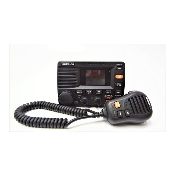
Page 11: Controls, Connections, And Indicators
Controls, Connections, and Indicators Controls, Connections, and Indicators Front Panel Rear Panel Connectors 1 HAILER connector 2 WHAM connector 3 GPS EXTSP (External Speaker) connector 4 DC jack 5 2.4GHz External WHAM x 4 Antenna 6 VHF Whip Antenna Controls, Connections, and Indicators... -
Page 12: Hailer Connector/Cable
Hailer Connector/Cable Connector Pinout Hailer 2 + Hailer 2 + Hailer 1 + Hailer 2 - Hailer 2 - Hailer 1 - Hailer 1 + Hailer 1 - To Hailer Connector GPS/External Speaker Connector/Cable Connector Pinout NMEA 0183 OUT - NMEA 0183 IN - NMEA 0183 OUT + NMEA 0183 IN +... -
Page 13: Setting Up The Radio
Caution: The UM625c is designed to use a nominal 13.8 volt negative ground battery system for power. Do not use a positive ground battery system to power the UM625c. Keep in mind the flexibility designed into the UM625c so that you can most conveniently use it. Features which should be considered are: •... -
Page 14: Choosing A Location
Choosing a Location Here are some important factors to consider in selecting the location for your UM625c. • While the UM625c is completely waterproof, it will last longer if protected from spray and splash. • Connect the UM625c directly to the battery for best operation. Always keep the battery leads as short as possible. -
Page 15: Using A Wham Or Wham X 4 Microphone With The Radio
WHAM or WHAM x 4 microphone for more information about connecting it to the radio. Important: If you want to use an external antenna for your WHAM x 4 with your UM625c marine radio, it must be installed by a professional installer. Do not attempt to connect an external antenna to a radio yourself. -
Page 16: A Look At The Radio
A Look at the Radio 1. PUSH/SELECT - Rotate to tune channels and highlight menu items you want to select, then press to select the channel you tuned or the item you selected. 2. MENU/HELP - Press to use the menu for the DSC Call, and Fog Horn. Hold down for 2 sec- onds to use the radio’s help function. -
Page 17: A Look At The Microphone
A Look at the Microphone PTT - Press to send a transmission. Release to hear a transmission. - Repeatedly press to tune channels and select menu items. 16/9 TRI - Press once to quickly tune to Coast Guard/Distress Channel 16. Press again to quickly tune to the secondary Hailing Channel 9. -
Page 18: Basic Operation
Basic Operation Turning the Radio On and Off Press PWR to turn on the radio. The radio sounds a tone and a screen showing the user MMSI appears if previously set. If you have not set a user MMSI, see “Setting Up a User MMSI” on Page 34. Note:If the radio is turned on for at least 3 seconds after you select a channel, it remembers the last channel you tuned when you turn it off. -
Page 19: Adjusting The Transmit Power
Adjusting the Transmit Power Press HI/LO/SCRAMBLER to adjust the transmit power. If the transmit power on the cur- rently tuned channel is set to Hi (25W), pressing HI/LO/SCRAMBLER changes it to Lo (1W), appears on the display. If the transmit power on the currently tuned channel is set to Lo, pressing HI/LO/SCRAMBLER changes it to Hi, and Important: The radio automatically sets itself to low transmit power if you tune to Channels 13, 67, 75, 76, 77 based on FCC rules. -
Page 20: Using Step
Using Step Step lets you quickly tune through the channels you saved in the radio's memory. To use step, repeatedly press STEP/SCAN. The radio tunes a channel you stored in memory each time you press STEP/SCAN. Using Hail Note: You must connect one or two optional hailer horns to the radio to use the hail feature. To enable the hail feature, press HAIL/INTERCOM. -
Page 21: Using Gps
Connect an external GPS unit to the NMEA0183 connection. The GPS unit then displays data and the UM625c displays its information in white to confirm valid data. If no valid data is repre- sent, the information is displayed in red. -
Page 22: Using Memory Channel
• Pressing 16/9 TRI stops the radio from scanning if the radio is set to Scan mode. • The radio cancels Coast Guard/Distress/Hailing mode if you press WX, MENU/HELP, HAIL/INTERCOM, or STEP/SCAN, hold down STEP/SCAN or HAIL/INTERCOM, or rotate PUSH/SELECT. Using Memory Channel Saving Channels in Memory You can save channels you tune into the radio's memory. -
Page 23: Using The Scrambler
• If you turn on Triple Watch while the radio is set to Coast Guard/Distress/Hailing mode, the radio scans primary Coast Guard/Distress/Hailing Channel 16, secondary Coast Guard/ Distress/Hailing Channel 9, and the last marine channel (Channel 16 or Channel 9). •... -
Page 24: Performing A Radio Self Test
Using SAME Alert The National Weather Service precedes each weather alert with a digitally encoded SAME (Specific Area Message Encoding) signal, then a 1050 Hz tone. The SAME signal includes a FIPS (Federal Information Processing Standard) area code, and an event code that corresponds with the type of alert being sent. -
Page 25: Receiving A Dsc Distress Call
3. Once sent, the radio monitors transmission between CH 16 and CH 70. until it receives an acknowledgement signal (ACK) 4. The radio sounds an alert which lasts between 210 and 270 seconds. The sound ceases upon receipt of an ACK. Notes: •... -
Page 26: Using The Dsc Call Menu
DSC CALL - Lets you select and work with DSC Call options. See “Using the DSC Call Menu”. DSC CALL INDIVIDUAL GROUP ALL SHIPS POS REQUEST POS SEND DSC STANDBY RECEIVE LOG DIRECTORY • FOG HORN - Lets you select and work with fog horn options. See “Setting the Fog Horn Options”... - Page 27 a. To select a station by vessel name, rotate PUSH/SELECT until the name of the station you want to talk to is highlighted, then press PUSH/SELECT to select it. b. To select a station by its user MMSI, rotate PUSH/SELECT until MANUAL is highlighted, then press PUSH/SELECT to select it.
- Page 28 2. To select the type of DSC ALL SHIPS call you want to send, rotate PUSH/SELECT until URGENCY or SAFETY is highlighted, then press PUSH/SELECT to send the DSC call. After the radio sends the DSC ALL SHIPS call, it automatically tunes to emergency Channel 16. If the radio receives an ALL SHIPS call, the radio sounds a tone.
- Page 29 A screen appears you can use to enter the station’s user MMSI. After you enter the user MMSI, press PUSH/SELECT. A screen appears where you can confirm or cancel sending a position. 3. To send your position using MANUAL mode, rotate PUSH/SELECT to select SEND , then press PUSH/SELECT to select send.
-
Page 30: Setting Dsc Call Options
3. To recall individual calls for a specific vessel, move the cursor to SEND, then press PUSH/ SELECT. Setting DSC Call Options Setting the DSC Call Directory This option lets you enter the name and MMSI number of up to 100 other vessels into the radio, work with existing entries in the directory, and delete directory entries. -
Page 31: Setting The Fog Horn Options
Deleting a Directory Entry 1. Select the entry you want to delete, rotate PUSH/SELECT to select DELETE , then press PUSH/SELECT to select it. A screen appears where you can delete the vessel’s information. 2. To delete the displayed directory entry, rotate PUSH/SELECT to select YES , then press PUSH/SELECT to confirm it. - Page 32 Status Power Boat Moving UNDERWAY Stopping STOP (default), ANCHORED, or AGROUND F o g H o rn S o u n d A u to m a tic M o d e – E x p la n a t io n A T U N D E R W A Y U s e s In fo rm a tio n fro m a c o n n e c te d G P S m o d u le to a u to m a tic a lly s o u n d th e c o rre c t h o rn a u d io fo r c u r re n t...
-
Page 33: The Setup Screen Options
The Setup Screen Options This chart shows the radio’s Setup Screen options if a WHAM base is not connected. THE SETUP SCREEN SUB MENU INITIALIZE RADIO USER MMSI VESSEL TYPE CHANNEL NAME FOG FREQUENCY FIPS BACKLIGHT AUTO CH SW KEYBEEP LEVEL POS REPLY COLOR PALLET GROUP MMSI... -
Page 34: Using The Initialize Sub Menu
MMSI. After you program a user MMSI for the first time, you can only change it once more. If you try to change the user MMSI a third time, the radio will not accept the change. To change the user MMSI again, you must return the radio to Uniden for reprogramming. -
Page 35: Setting The Vessel Type
Setting the Vessel Type This option lets you select whether your vessel is a motor vessel, sailing vessel, or tow boat. This lets you select the correct fog horn settings for your particular vessel. 1. Rotate PUSH/SELECT to select VESSEL TYPE , then press PUSH/SELECT to select it. 2. -
Page 36: Setting The Local Time - Time Adjust And Time Entry
Setting the Local Time - Time Adjust and Time Entry If you connect an optional GPS module to the radio, the radio automatically sets the local time. Follow these steps to manually enter the local time. 1. Rotate PUSH/SELECT to select TIME ADJUST , then press PUSH/SELECT to select it. A menu screen appears to let you select AUTO or MANUAL . -
Page 37: Using The Radio Sub Menu
Setting UIC Waters Option With a GPS connected and operating, the radio automatically alerts you by means of a pop- up screen that states you are entering another area’s waters if the UIC is currently set to a location but the vessel is actually in another’s territorial waters. For example, the radio alerts you if the UIC is set to USA but the vessel is actually in Canadian waters. -
Page 38: Setting Fips Codes
4. Repeat Step 3 for each of the channel name’s characters. When you have entered all of the channel name’s characters, hold down PUSH/SELECT. When you have entered all of the channel name’s characters, a confirmation screen appears. 5. If the channel name you set appears correctly, rotate PUSH/SELECT to select YES. The radio saves the channel name you input. -
Page 39: Disabling Auto Channel Switch
4. Repeat Step 3 for each of the FIPS code’s numbers. When you have entered all of the FIPS code numbers, hold down PUSH/SELECT. A confirmation screen appears. 5. If the FIPS code you set appears correctly, rotate PUSH/SELECT to select YES. The radio saves the FIPS code you input. -
Page 40: Setting Channel Scan
3. Repeat Step 2 for each of the group MMSI's digits. When you have entered each of the group MMSI's digits, a confirmation screen appears. 4. If the displayed group MMSI is correct, rotate PUSH/SELECT to select YES , then press PUSH/SELECT to confirm it. -
Page 41: Using The Wham And Wham X 4 Sub Menus
Using the WHAM and WHAM x 4 Sub Menus (Wireless Handheld Access Microphone) This option lets you set up a WHAM (900MHz — up to 2 mics) or WHAM x 4 (2.4GHz — up to 4 mics) wireless microphone to operate with the radio. You must first set up a WHAM or WHAM x 4 microphone before it will work with the radio. - Page 42 Setting a WHAM Base ID The WHAM base ID for the radio and the WHAM microphone you are installing must be set to the same number. 1. Rotate PUSH/SELECT to select BASE ID , then press PUSH/SELECT to select it. The cursor moves to the first character of the base ID.
-
Page 43: Using The Hailer Rename Option
Using the Hailer Rename Option 1. Scroll, using PUSH/SELECT to reach HAILER RENAME . Push the knob once. 2. Rotate the PUSH/SELECT to select a listed name. Push to select it. Rotate the knob to reverse highlight a desired new character. Push to select it. Select YES to keep your changes, NO to discard them. - Page 44 The XTRACK screen can be selected under the following circumstances: Your radio is set to a standard channel. Then you receive a Distress call. Your radio immedi- ately switches to DISTRESS CALL received screen. If a GPS module is either not attached or not providing data to the radio, NO DATA FROM GPS appears instead and the radio sounds a tone.
-
Page 45: Viewing The Compass Screen
4. If you are so far off course that the XTRACK screen cannot properly indicate the correct action, an OUT OF RANGE warning appears. 5. Since your GPS knows where you are and since you have a starting location, the system automatically displays the NOW ARRIVING screen when the radio is updated by the GPS with new data and you are less than .02 miles from your destination. -
Page 46: Using The Digital Menu
Then rotate PUSH/SELECT to select the desired help options. Next, press PUSH/SELECT to select one. Care and Maintenance Your UM625c Marine Radio is a precision electronic instrument and you should treat it accordingly. Due to its rugged design, very little maintenance is required. However, a few precautions should be observed. -
Page 47: Specifications
A: The microphone might have a bad element. Contact your Uniden marine dealer for more information. Q: The radio always stops on one particular channel even though I didn’t select it. Why? A: There might be a source of noise near that channel’s frequency. Choose another frequency. - Page 48 Transmitter - Marine Radio Power Output LO 1 watt HI 25 watts Power Requirement (Output) LO Not rated HI 5.6A at 13.8V DC Modulation FM ±5 kHz deviation (FCC designator F3E) Audio Distortion Less than 8% with 3 kHz deviation with 1000 Hz modulating frequency Spurious Suppression -25 dBm @ Hi, -25 dBm @ Lo Output Power Stabilization Built-in automatic level control (ALC) Frequency Range 156 to 158 MHz...
- Page 49 Public Address/Listen Back Output Power @ Max. Volume PA1/PA2 Microphone Input 10mV, 1 KHz (4 PA1 + PA2 Microphone Input 10mV, 1KHz (2 Listen Back Sensitivity (Hail 1/Hail 2) 5 mV WHAM x 4 Base Specifications Measurement Conditions Power Source External Antenna Impedance Test Temperature Reference Audio Output Power...
-
Page 50: Appendix
Appendix NMEA Operation This radio supports NMEA0183 version 3.01. NMEA Input The radio supports RMC, GLL, GNS, GGA and ZDA sentences. When these sentences are received, the radio displays latitude/longitude, date, time, course, and speed. If any sentence except an RMC or GLL sentence is received, the radio uses the information based on the following priority order. -
Page 51: Reference Information
Reference Information USA/Canadian/International Channel Frequencies 1”A” 156.0500 3”A” 156.1500 5”A” 156.2500 156.3000 7”A” 156.3500 156.4000 156.4500 156.5000 156.5500 156.6000 156.6500 156.7000 156.7500 156.8000 156.8500 18”A 156.9000 ” 19”A 156.9500 ” 20”A 157.0000 ” 21”A 157.0500 ” 22”A 157.1000 ” 23”A 157.1500 ”... - Page 52 64”A 156.2250 ” 65”A 156.2750 ” 66”A 156.3250 ” 156.3750 156.4250 156.4750 156.5250 156.5750 156.6250 156.6750 74” 156.7250 156.775 156.825 156.8750 78”A 156.9250 ” 79”A 156.9750 ” 80”A 157.0250 ” 81”A 157.0750 ” 82”A 157.1250 ” 83”A 157.1750 ” 84” 161.8250 161.8750 161.9250...
- Page 53 160.6500 160.7000 160.7500 4”A” 156.2000 5”A” 156.2500 156.3000 7”A” 156.3500 156.4000 156.4500 156.5000 156.5500 156.6000 156.6500 156.7000 156.7500 156.8000 156.8500 18”A 156.9000 ” 19”A 156.9500 ” 161.6000 21”A 157.0500 ” 22”A 157.1000 ” 161.7500 161.8000 161.8500 161.9000 161.9500 162.0000 160.6250 61”A 156.0750 ”...
- Page 54 62”A 156.1250 ” 160.8250 64”A 156.2250 ” 65”A 156.2750 ” 66”A 156.3250 ” 156.3750 156.4250 156.4750 156.5250 71” 156.5750 156.6250 156.6750 156.7250 156.775 156.825 156.8750 78”A 156.9250 ” 79”A 156.9750 ” 80”A 157.0250 ” 81”A 157.0750 ” 82”A 157.1250 ” 83”...
- Page 55 162.0250 160.6500 160.7000 160.7500 160.8000 160.8500 156.3000 160.9500 156.4000 156.4500 156.5000 156.5500 156.6000 156.6500 156.7000 156.7500 156.8000 156.8500 161.5000 161.5500 161.6000 161.6500 161.7000 161.7500 161.8000 161.8500 161.9000 161.9500 162.0000 160.6250 Appendix Status Full Name 157.4250 Duplex MARINE OPERATOR 156.0500 Duplex MARINE OPERATOR 156.1000 Duplex...
- Page 56 160.6750 160.7250 160.7750 160.8250 160.8750 160.9250 156.3750 156.4250 156.4750 156.5250 156.5750 156.6250 156.6750 156.7250 156.775 156.825 156.8750 161.5750 161.5750 161.6250 161.6750 161.7250 161.7750 161.8250 161.8750 161.9250 161.9750 162.0250 Status Full Name 156.0750 Duplex MARINE OPERATOR 156.1250 Duplex MARINE OPERATOR 156.1750 Duplex MARINE OPERATOR 156.2250...
-
Page 57: Weather Channel Frequencies
Weather Channel Frequencies Ch. No. Description (Receive Only) RX Frequency WX01 Weather Information 162.5500 WX02 Weather Information 162.4000 WX03 Weather Information 162.4750 WX04 Weather Information 162.4250 WX05 Weather Information 162.4500 WX06 Weather Information 162.5000 WX07 Weather Information 162.5250 WX08 Weather Information 161.6500 WX09 Weather Information... - Page 58 Standard Event Code National Audible Test National Information Center Network Notification Message National Periodic Test National Silent Test Nuclear Power Plant Warning Power Outage Advisory Radiological Hazard Warning Required Monthly Test Required Weekly Test Special Marine Warning Special Weather Statement Shelter In-Place Warning Severe Thunderstorm Watch Severe Thunderstorm Warning...
-
Page 59: Three Year Limited Warranty
WARRANTOR: UNIDEN AMERICA CORPORATION (“Uniden”) ELEMENTS OF WARRANTY: Uniden warrants, for three years, to the original retail owner, this Uniden Product to be free from defects in materials and craftsmanship with only the limita- tions or exclusions set out below.
Need help?
Do you have a question about the UM625C and is the answer not in the manual?
Questions and answers
Channels don’t appear on the screen