Table of Contents
Advertisement
Quick Links
Advertisement
Table of Contents

Summary of Contents for VARSITY Scoreboards VSBX-742LED
- Page 1 INSTALLATION INSTRUCTIONS Model VSBX-742LED www.varsityscoreboards.com...
-
Page 2: Table Of Contents
Table of Contents DESCRIPTION ................................3 THE SCOREBOARD SYSTEM SHOULD INCLUDE THE FOLLOWING PARTS: ......3 INSTRUCTIONS FOR REPORTING SHIPPING DAMAGE ................. 3 INSTALLATION OVERVIEW ..........................4 PRODUCT SPECIFICATIONS ..........................4 Overall Dimensions: ............................4 Weight: ..................................4 Mounting Requirements: ..........................4 Power Requirements: ............................ -
Page 3: Description
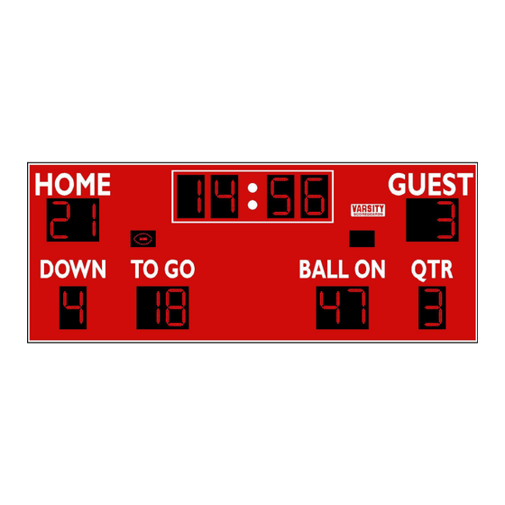
DESCRIPTION MODEL VSBX-742LED OUTDOOR SCOREBOARD NOTE TO INSTALLERS: PLEASE RETURN THIS MANUAL TO THE INDIVIDUAL IN CHARGE OF THE SCOREBOARD UPON COMPLETION OF INSTALLATION. The scoreboard and all accompanying accessories have been carefully inspected and tested before leaving the factory. However, it is possible for damage to have occurred during shipping. Therefore, we ask that you inspect all shipping containers upon arrival for damage and ensure that you have all of the parts listed below. -
Page 4: Installation Overview
If damage is discovered after delivery, call the delivery company to report the concealed damage and please call the manufacturer immediately to report. Concealed damage must be reported within 5 days after the delivery date. If the damages are found after this time, the manufacturer will not be responsible. -
Page 5: Communication Cable Requirements (For Cable-Controlled Systems Only)
• Access must be provided to turn off the power to the scoreboard after each use. Failure to turn off the power to the scoreboard could affect the functionality of the scoreboard; such as from a power surge or lightning strike. •... -
Page 6: Installing The Mounting Poles/Beams
NOTE: The length of Beam/Pole above ground should be calculated by including the height of top and/or bottom sponsor panels if they are part of the installation INSTALLING THE MOUNTING POLES/BEAMS 1. The following information for installing the mounting poles/beams is for suggestions only. Local codes, field placement, scoreboard options, customer preference, and other special considerations will determine the above ground height and total length of the poles/beams. - Page 7 NOTE: CONSULT WITH LOCAL BUILDING CODE OFFICIALS REGARDING THE REQUIRED DIMENSIONS AND CONSTRUCTION OF THE FOOTERS, POLE/BEAM SIZES, AND OTHER REQUIREMENTS AND RESTRICTIONS REGARDING THE INSTALLATION OF THE SCOREBOARD. DETERMINING INSTALLATION TYPE IMPORTANT NOTE: The main consideration when choosing installation type A or B is whether the lifting device you will use is capable of supporting the weight of the entire assembly.
- Page 8 4. Install crossover nipples between cabinets A, B, & C in one section and between cabinets D and E, in the other section. Failure to install crossover nipples will void the warranty. 5. Connect ALL crossover cables between cabinets as in the “Cable Connections” image above, making sure the red stripe on the edge of the ribbon cables are aligned when connected.
- Page 9 13. NOTE: IF THE WIRES IN YOUR CABLE DO NOT COLOR MATCH WHAT IS SHOWN ABOVE, CONNECT TO THE TERMINALS WITH THE BLACK, GREEN, AND WHITE CONDUCTORS. DO NOT CONNECT A WIRE TO THE RED TERMINAL. MATCH THE SAME COLORS IN YOUR CABLE TO THE BLACK, GREEN, AND WHITE WIRES ON THE BACK OF THE WALL PLATE AT THE SCORING LOCATION.
- Page 10 5. Connect ALL crossover cables between cabinets as in the image on the right above, making sure the red stripe on the edge of the ribbon cables are aligned when connected. 6. Lift the assembly from the top angle irons to a vertical position, still resting on the ground and install the top sponsor panel if included in the installation.
- Page 11 15. Install any options such as horns or protective screens. 16. Run and connect the control cable for cable controlled systems. No cable is required for wireless systems. 17. NOTE: IF THE WIRES IN YOUR CABLE DO NOT COLOR MATCH WHAT IS SHOWN ABOVE, CONNECT TO THE TERMINALS WITH THE BLACK, GREEN, AND WHITE CONDUCTORS.
- Page 12 NOTE: IF THE WIRES IN YOUR CABLE DO NOT COLOR MATCH WHAT IS SHOWN ABOVE, CONNECT TO THE TERMINALS WITH THE BLACK, GREEN, AND WHITE CONDUCTORS. DO NOT CONNECT A WIRE TO THE RED TERMINAL. MATCH THE SAME COLORS IN YOUR CABLE TO THE BLACK, GREEN, AND WHITE WIRES ON THE BACK OF THE WALL PLATE AT THE SCORING LOCATION.
-
Page 13: Running/Connecting The Electrical Service
NOTE: Even if the control cable was not buried in conduit, it must be run in sealed, watertight, conduit from the ground up to the signal cable/power access door located on the back of the scoreboard. Here, it must pass through a rain-tight conduit fitting where it will connect to the signal cable terminal block inside the scoreboard. - Page 14 a. NOTE: None of the scoreboards components should be lit at this time. If any components are lit, especially with a solid “8”, check the crossover connections between cabinets. Ensure that the red stripes on the ribbon cables are matched where they are connected.
-
Page 15: Important
IMPORTANT! Warranty Activation/Installation & Completion Sign Off Sheet NOTE: This sheet must be completely filled out and returned/faxed (270) 753-3773 to Scoreboard Service Company before your warranty can be activated. Your Serial Number _______________________________________ Your Model Number _______________________________________ Date Purchased _______________________________________ Sales Agent _______________________________________...


Need help?
Do you have a question about the VSBX-742LED and is the answer not in the manual?
Questions and answers