Table of Contents
Advertisement
Quick Links
Advertisement
Table of Contents

Subscribe to Our Youtube Channel
Related Manuals for Arjo Evenda


Summary of Contents for Arjo Evenda
- Page 1 INSTRUCTIONS FOR USE Evenda 4 castor version 04.EV.01_EN_01 • 03/2023...
- Page 2 © Arjo 2023. As our policy is one of continuous improvement, we reserve the right to modify designs without prior notice. The content of this publication may not be copied either whole or in part without the consent of Arjo.
-
Page 3: Table Of Contents
Contents Foreword ................5 Intended use . - Page 4 Simplified hand control (optional) ............28 Anti-slide position .
-
Page 5: Foreword
Unauthorised modifications on any Arjo equipment can affect safety. Arjo will not be held responsible for any accidents, incidents or lack of performance that occur as a result of any unauthorised modification to its products. -
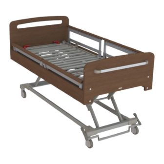
Page 6: Intended Use
Intended use The Evenda bed is a height and contour adjustable bed for use in a long-term professional care setting where medical supervision is provided. The bed is to be operated by appropriately trained caregivers attending to the care of residents/patients and by residents/patients determined to be clinically capable. - Page 7 The equipment must be installed in accordance with guidance provided in the Instructions for Use. Expected Service Life The expected service life of the Evenda bed is 10 years. Service life is defined as the period during which the product will maintain the specified performance and safety, provided it has been maintained and operated in conditions of normal use in accordance with the requirements in the Instruction for Use.
-
Page 8: Safety Instructions
Safety instructions WARNING WARNING To avoid injury, each patient should be To avoid injury make sure that patient weight, clinically assessed by a qualified person accessory weight and mattress weight do not before using the bed. exceed the Safe Working Load of the bed. If the maximum patient weight for the mattress is different than that specified for the bed, the lower value applies. - Page 9 WARNING WARNING To avoid strangulation or impaired Keep pets and children away from the bed circulation, use the hand control clip and unless they are supervised by an adult. position the hand control and the cable correctly. CAUTION To avoid equipment damage, do not let the hand control cable get damaged by the bed or WARNING other objects being moved over it.
-
Page 10: Preparation
7. Store the IFU in a designated area, where it is easily accessible at all times. Before every use 1. Inspect the Evenda bed according to the Care and preventive maintenance chapter in this IFU. If any item is damaged – do NOT use the product. - Page 11 (4.7 - 8.7 in) • 220 cm (86.6 in) *Suitable mattress length depends on if the Evenda bed has been extended. Powered air mattressess Powered air/foam mattresses might be thicker than a foam mattress. Replacement to a powered air/ foam mattress must be assessed individually prior to use to verify that enough space for the bed rails is maintained.
- Page 12 Initial startup Turning on/off the bed CAUTION To ensure proper performance, leave the bed connected to a power outlet for at least 10 hours after plugging it in for the first time with the battery installed. NOTE If using a power outlet controlled by a power switch, make sure the power switch is set to 1.
- Page 13 • If the backrest adjustment LED is flashing, lower the backrest section all the way down, then raise it to the desired position. • If the thigh section adjustment LED is flashing, lower the thigh section all the way down, then raise it to the desired postition.
-
Page 14: Parts Designation
Parts designation The 4 castor configuration bed is always equipped with bed rails. 1. Accessory socket (one on each side) 9. Mattress retainer (two per side) 2. Headboard 10. Brake pedal 3. Magnet for lockout (one on each side of the 11. - Page 15 Accessories All accessories are optional. 1. Wall spacer 5. Plastic covers for the mattress platform 2. Battery 6. Footboard (different designs) 3. CPR release handle 7. Brake bar 4. Flexible hand control holder 8. DIN rail with hooks PARTS DESIgNATION...
- Page 16 Hand controls Standard hand control (model HB100) 1. Power indicator 2. Lockout indicator and magnetic sensor area 3. Function LED indicator 4. Backrest adjustment 5. Comfort chair adjustment 6. Height adjustment 7. Thigh section adjustment 8. Flat and programmed height Optional hand control with tilt function (model HL70) Simplified hand control 1.
-
Page 17: Product Description - Bed
Product description - Bed Brakes The brake pedals are located at the foot end. The brake pedals can be linked by a full-width bar. The brakes have three positions: brake, free and steer. Brake: The brakes are applied on all four castors. Figure 3 See Figure 3. -
Page 18: Magnets For Function Lockout
Magnets for function lockout See Figure 6 There are four magnets: one on each side of the headboard and footboard. The magnets are used for function lockout on the standard hand control. See Lockout on the standard hand control on page Backrest Figure 6 The backrest is adjusted with the hand control. -
Page 19: Footboard
Footboard See Figure 9 The footboard has three positions to allow the caregiver to adjust the bed length for tall patients. See Extending the bed frame on page 33. The footboard cannot be removed. Mattress retainers Figure 9 WARNING To avoid unintentional mattress movement and falling, make sure that all four mattress retainers are installed correctly and that the mattress sits within all mattress retainers. -
Page 20: Telescopic Bed Rails (Optional)
Telescopic bed rails (optional) See Figure 12. The bed can be equipped with telescopic bed rails to secure the patient along the full bed length. When raised, the telescopic bed rails can be locked in the highest position or in one of several middle positions. -
Page 21: Product Description - Accessories
Product description - Accessories Wall spacer (optional) See Figure 15 The wall spacer prevents the power cord and any electrical outlets from being damaged by the bed. • When the bed is stationary, keep the wall spacer lowered. • For transport, keep the wall spacer raised against the bed legs. -
Page 22: Flexible Hand Control Holder (Optional)
Flexible hand control holder (optional) See Figure 18 The hand control holder can be installed onto either side of the backrest frame. It provides the patient with easy access to the hand control. To avoid collision with other accessories, the hand control holder should be positioned between the second and third bar. -
Page 23: Plastic Covers For The Mattress Platform (Optional)
Plastic covers for the mattress platform (optional) See Figure 22 The plastic covers can be placed on the mattress platform for easy cleaning of bed surfaces. Once fitted, the mattress platform extension should be placed on top of the plastic cover. Figure 22 Footboard with accessory rail (optional) -
Page 24: Din Rail With Hooks (Optional)
DIN rail with hooks (optional) See Figure 25 CAUTION To avoid damage to the DIN rail, do not exceed its Safe Working Load. CAUTION To avoid damage to the drainage bag by compression, pay attention when lowering the bed to the lowest position. The DIN rail can be hung on the bed frame or side panel using clipping hooks. -
Page 25: Product Description - Hand Controls
Product description - Hand controls NOTE When any button is pressed on the Standard hand control, a backlight turns on and stays on for 15 seconds. Standard hand control and Optional hand control with tilt function See Figure 26 Figure 26 Power indicator (standard hand control only) See Figure 27 The Power indicator light is green when the bed is... -
Page 26: Backrest Adjustment
Backrest adjustment See Figure 30 The Backrest adjustment buttons raise and lower the backrest. The backrest pauses briefly at 30° and at 45°. Figure 30 Comfort chair adjustment See Figure 31 The Comfort chair up button first raises the backrest and the thigh section, then tilts the bed forwards into a chair position. -
Page 27: Thigh Section Adjustment
Thigh section adjustment See Figure 33 The Thigh adjustment buttons raise and lower the thigh section. The thigh section pauses briefly at 30°. To adjust the calf section, see on page 43. Figure 33 Flat and programmed height (standard hand control only) See Figure 34 The Flat and programmed height button returns the... -
Page 28: Under Bed Light (Optional)
Under bed light (optional) When the bed is plugged in, the under bed light is constantly turned on. If the bed operates on battery power, the under bed light only turns on when the hand control is used. The light turns off automatically after 2 minutes if no action is performed. -
Page 29: Anti-Slide Position
Anti-slide position See Figure 37 The Anti-slide position button raises the backrest and the thigh section to help prevent the patient from sliding. Figure 37 If the function is activated when the bed is tilted, the mattress platform is first brought to a horizontal position. -
Page 30: Product Functions
Product functions Lockout on the standard hand control WARNING To avoid injury and unintentional activation, each patient should be clinically assessed by a qualified person before being allowed to operate the hand control. By setting the lockout configuration, the caregiver can select bed functions to be locked for use. - Page 31 NOTE If a function button is pressed while the function is locked, the lockout indicator flashes. Temporary unlocking on the standard hand control 1. Hold the hand control magnetic sensor against the magnet for 1 second. See Figure 41. Both the front and the back of the hand control are possible to use.
-
Page 32: Lockout On The Optional Hand Control With Tilt Function
Lockout on the optional hand control with tilt function WARNING To avoid injury and unintentional activation, each patient should be clinically assessed by a qualified person before being allowed to operate the hand control. By setting the lockout configuration, the caregiver can select bed functions to be locked for use. -
Page 33: Extending The Bed Frame
Extending the bed frame WARNING To avoid entrapment, adjust the footboard and the calf section to the same length and make sure both are securely tightened in position. The bed can be extended from 200 cm (78 ½ in) to 210 cm (82 ½... - Page 34 5. Lift the plastic end of the mattress platform extension. See Figure 48. 6. Pull the metal frame to the same length as the footboard. See Figure 49. 7. Put down the mattress platform extension over the stopper to lock the position. See Figure 50. 8.
-
Page 35: Installing Bed Rail Gap Fillers
Installing bed rail gap fillers WARNING To avoid entrapment, always install bed rail gap fillers after extending the mattress platform if the bed is equipped with telescopic bed rails. 1. With the mattress platform extended, position the bed rail gap filler over one of the holes in the Figure 52 footboard bracket. -
Page 36: Telescopic Bed Rails
Telescopic bed rails WARNING To avoid risks of falls, always assess how prone to falls the patient is. If the patient is at risk of falling, leave the telescopic rails in the highest position while the patient is unattended. The middle position is not sufficient to prevent falls. - Page 37 NOTE Install bed rail gap fillers if the telescopic bed rails are used when the bed is extended. See Installing bed rail gap fillers on page 35 Lowering the telescopic bed rails 1. Press and hold the buttons and lower the telescopic bed rail to the lowest position.
-
Page 38: ¾ Folding Bed Rails
¾ Folding bed rails WARNING To avoid entrapment, only use bed rails designed and specified for use with this bed. WARNING To avoid falling, the patient must not put their full weight on the bed rail. WARNING To avoid pinching, be careful when adjusting and operating the bed rails. -
Page 39: Battery
Lowering the ¾ folding bed rail 1. Hold the top rail. WARNING To avoid pinching, keep hands away from Figure 63 the bed rail when lowering. Pull out the blue operating knob and lower the bed rail towards the foot end of the bed. See Figure 63 and Figure 64 Figure 64 Battery... - Page 40 Charging the battery If there is a constant beep when operating the bed, the battery needs to be charged. Connect the bed to a power outlet. The battery indicator on the battery indicates the charging status of the battery. • Solid yellow: Charging •...
-
Page 41: Cpr Position
CPR position CAUTION To avoid equipment damage, only use the CPR release handle in an emergency. Repeated everyday use can cause permanent wear. CPR position with CPR handle 1. Lower the bed rails. WARNING Figure 65 To avoid entrapment, keep hands clear when using the CPR release handle. -
Page 42: Preparing The Bed For A Patient
Preparing the bed for a patient Preparing the bed (15 steps) 1. Turn on the bed, see Turning on/off the bed on page 12. WARNING Figure 68 To avoid falling during unintentional bed movement, apply the brakes when the bed is stationary. - Page 43 11. Lower the bed rails. 12. Transfer the patient following local regulations, proceedures, safety rules, protocols and patient placement instructions for the mattress used with the bed. 13. Based on the patient assessment, raise and lock bed rails on both sides of the bed. WARNING To avoid falling, apply brakes when the patient is left unattended.
-
Page 44: Additional Patient Positions
Additional patient positions Calf section adjustment • To raise the calf section, lift the calf section until it locks at the desired height. See Figure 71. • To lower the calf section, lift the calf section to the maximum height and then lower it. See Figure 72. Straight leg position •... -
Page 45: Transporting Patients
Transporting patients The Evenda bed with 4-castor configuration can be used for transportation of patients. WARNING To avoid injury from falling, make sure the bed rails are fully raised during transportation. Raise the bed rails and make sure they are locked. -
Page 46: Cleaning And Disinfection
Cleaning and disinfection WARNING To avoid cross-contamination or equipment damage, Arjo recommends that the bed be cleaned during use and between patients according to the instructions in this IFU. Local protocols and regulations / procedures for blood borne pathogens may be used provided the manufacturer’s instructions are followed. - Page 47 Cleaning and disinfecting the bed (9 steps) Cleaning (7 steps) 1. Disconnect the power cord from the power outlet. 2. Remove the mattress and the accessories from the bed. Do not remove bed rails or mobility assist handle. 3. Wearing suitable protective clothing, clean all surfaces with a disposable cloth moistened in hand-hot water and a neutral detergent, or an appropriate disposable cleaning wipe.
-
Page 48: Care And Preventive Maintenance
Care and preventive maintenance This product is subject to wear and tear during use. To make sure that it continues to perform within its original specification, functionality checks should be carried out at the intervals shown. More frequent checks should be carried out when the product is subjected to heavy use, aggressive environments or where required by local regulations. - Page 49 Yearly checks by qualified service personnel only WARNING To avoid injury or electric shock, always disconnect the bed from the power outlet before starting any maintenance activity. WARNING To avoid injury and/or unsafe product, the maintenance activities must be carried out at the correct frequency by qualified personnel using correct tools, parts and knowledge of procedure.
-
Page 50: Troubleshooting
Troubleshooting If the equipment fails to operate correctly, the table below suggests some simple checks and corrective actions. If these steps fail to resolve the problem, contact Arjo or an Arjo-approved service agent. PROBLEM POSSIBLE CAUSE ACTION DESCRIPTION Follow the hand control unlocking Functions are locked on the hand procedure. - Page 51 Contact Arjo or an Arjo function when plugged into the control box. representative. power outlet. Contact Arjo or an Arjo representative Bed does not have the battery if you want to install a battery accessory installed. accessory. Contact Arjo or an Arjo representative Battery is past its expiry date.
- Page 52 PROBLEM POSSIBLE CAUSE ACTION DESCRIPTION Loosen the screws. If the screws are too tight to remove Cannot adjust footboard. Screws are tightened. by hand, contact your service representative. Tighten the screws the underside of the bed frame. Headboard or footboard are Screws are loose.
-
Page 53: Technical Specifications
Technical specifications GENERAL Safe working load 230 kg (507 lb) Maximum patient weight 195 kg (430 lb) Product weight 165 kg (364 lb) - Fully assembled < 15.8 kg (34.8 lb) - Headboard < 15.8 kg (34.8 lb) - Footboard Total weight of equipment, including 395 kg (871 lb) Safe working load... - Page 54 BED ADJUSTMENTS Bed height (distance from floor to the top 310 to 800 mm (12 ¼ to 31 ½ in) - with 125 mm castors of the mattress platform) 335 to 825 mm (13 ¼ to 32 ½ in) - with 150 mm castors Mattress platform tilt -12°...
- Page 55 SITE REQUIREMENTS Indoor/outdoor use Indoor use Maximum floor slope 10° Door passages width Min 1000 mm (39.4 in) Voltages 100 - 240 VAC Frequency 50 Hz, 60 Hz Power input 420 VA Number of phases Single phase AC Protective earth Class I: yes Power requires Live and Neutral.
- Page 56 OPERATING CONDITIONS Temperature +5 °C to +30 °C (+41 °F to +86 °F) Relative humidity 20 % to 80 % non-condensing Atmospheric pressure 700 to 1060 hPa TRANSPORT AND STORAGE CONDITIONS Temperature -25 °C to +50 °C (-13°F to +122 °F) Relative humidity 20 % to 90 % non-condensing Atmospheric pressure...
-
Page 57: Labels
Labels 1. Mattress size label 4. Gap filler label 2. Product label - States the product identification 5. Magnet label (4 in total) and technical specification. 6. Product name label 3. Patient size label 7. Hazard label L ABELS... - Page 58 SYMBOL EXPLANATION Refer to instruction manual/booklet (Instructions for use) Operating instructions (Instructions for use) CE marking indicating conformity with European Community harmonised legislation. Indicates the product is a Medical Device according to EU Medical Device Regulation 2017/745. Serial number Reference number Unique device identifier Name and address of the manufacturer Manufacturing date...
- Page 59 IEC 60601-2-52:2009 + AMD1:2015 CSA-C22.2 No. 60601-2-52:2011 + AMD1:2015 * The Evenda bed is not a home use device. Hence the application of the standards ANSI/AAMI HA60601-1-11:2015 and CSA C22.2 No. 60601-1- 11:2015 does not apply to the home environment. Home environment is not considered to be environment providing professional healthcare.
- Page 60 UK SYMBOL EXPLANATION This section is only applicable to United Kingdom (UK) market when UK marking is applied to the Arjo medical device labelling. UK marking indicating conformity with UK Medical Devices Regulations 2002 (SI 2002 No 618, as amended) UK Responsible Person &...
-
Page 61: Electromagnetic Compatibility
The product has been tested for compliance with current regulatory standards regarding electromagnetic interference in accordance with the information provided in this document. The Evenda long term care bed is intended for use in the following electromagnetic environments: Home healthcare environment. - Page 62 GUIDANCE AND MANUFACTURER’S DECLARATION – ELECTROMAGNETIC EMISSION Emissions test Compliance Guidance Conducted disturbances (conducted This equipment is suitable for use in Class B, group I emissions) CISPR 11 all establishments, including domestic establishments and those directly connected Electromagnetic radiation disturbance Class B, group I to the public low voltage power supply (radiated emissions) CISPR 11...
- Page 63 GUIDANCE AND MANUFACTURER’S DECLARATION – ELECTROMAGNETIC IMMUNITY Electromagnetic environment – Immunity test IEC60601 test level Compliance level guidance Electrical fast ± 1 kV SIP/SOP ports, ± 1 kV SIP/SOP ports, Mains power supply should be that transient/burst ± 2 kV AC port ±...
-
Page 64: Parts And Accessories
Parts and accessories ACCESSORY PRODUCT CODE Lifting pole with strap and handle EV-ACC01 Gap filler for telescopic bed rails (pair) EV-ACC02 Wallspacer EV-ACC22 IV pole ENT-ACC02 Angled IV pole ENT-ACC04 Heavy duty IV pole ENT-ACC24 Battery Backup EV-ACC21 DIN rail with 2 hooks EV-ACC04 Urine Bottle Holder EV-ACC07... - Page 65 Intentionally left blank...
- Page 66 Intentionally left blank...
- Page 67 AUSTRALIA FRANCE POLSKA Arjo Australia Arjo SAS Arjo Polska Sp. z o.o. Building B, Level 3 2 Avenue Alcide de Gasperi ul. Ks Piotra Wawrzyniaka 2 11 Talavera Road CS 70133 PL-62-052 KOMORNIKI (Poznań) Macquarie Park, NSW, 2113, FR-59436 RONCQ CEDEX...
- Page 68 At Arjo, we believe that empowering movement within healthcare environments is essential to quality care. Our products and solutions are designed to promote a safe and dignified experience through patient handling, medical beds, personal hygiene, disinfection, diagnostics, and the prevention of pressure injuries and venous thromboembolism. With over 6500 people worldwide and 65 years caring for patients and healthcare professionals, we are committed to driving healthier outcomes for people facing mobility challenges.
Need help?
Do you have a question about the Evenda and is the answer not in the manual?
Questions and answers