Table of Contents
Advertisement
Quick Links
Butterfly valve
Operating manual
Version
BA-2023.06.21 EN
Print-No.
302 520
TR MA DE Rev001
Series K 210
STÜBBE GmbH & Co. KG
Hollwieser Straße 5
32602 Vlotho
Germany
Tel: +49 (0) 5733-799-0
Fax: +49 (0) 5733-799-5000
E-mail:
contact@stuebbe.com
Internet:
www.stuebbe.com
Subject to technical modifications.
Read carefully before use.
Save for future use.
Advertisement
Table of Contents

Related Manuals for Stübbe K 210 Series


Summary of Contents for Stübbe K 210 Series
-
Page 1: Tab
Butterfly valve Operating manual Series K 210 Version BA-2023.06.21 EN STÜBBE GmbH & Co. KG Print-No. 302 520 Hollwieser Straße 5 TR MA DE Rev001 32602 Vlotho Germany Tel: +49 (0) 5733-799-0 Fax: +49 (0) 5733-799-5000 E-mail: contact@stuebbe.com Internet: www.stuebbe.com Subject to technical modifications. -
Page 2: Table Of Contents
Table of contents Table of contents About this document ....... Troubleshooting . -
Page 3: About This Document
About this document About this document Other applicable documents This manual • is part of the fitting Resistance lists • applies to all series referred to Resistance of materials used to chemicals • it describes safe and proper operation during all operating phases www.stuebbe.com/pdf/300051.pdf Target groups... -
Page 4: Safety Instructions
Safety instructions Safety instructions 2.2.2 Obligations of personnel • Observe the instructions on the fitting and keep them leg- ible, e.g. name plate and identification marking for fluid The manufacturer accepts no liability for damages caused connections. by disregarding any of the documentation. •... -
Page 5: Layout And Function
Layout and Function Layout and Function Marking K 210 Hollwieser Str. 5, DE-32602 Vlotho 147914 Id No 10 / 50 PN/DN 1407-87345 PP • EPDM Fig. 1 Name plate (example) Type ID number Nominal pressure [bar] / Nominal diameter [mm] Materials (housing and seals) Date of manufacture - Series number Description... -
Page 6: Transport, Storage And Disposal
Transport, Storage and Disposal Transport, Storage and Storage Disposal NOTE Material damage due to inappropriate storage! Unpacking and inspection on delivery Store the fitting properly. 1. Unpack the fitting when received and inspect it for trans- 1. Make sure the storage room meets the following condi- portation damage. -
Page 7: Installation And Connection
Installation and connection Installation and connection Installing fitting in pipe WARNING Preparing for installation Risk of poisoning and environmental damage from 5.1.1 Check operating conditions medium! 1. Ensure the design of the fitting is consistent with the pur- Leak due to faulty installation. pose intended: Installation work on the pipes should only be performed –... -
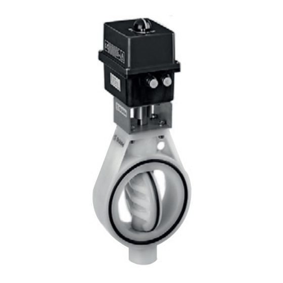
Page 8: Drive
Installation and connection Drive Limit switch box can only be used with pneumatic drive. Fig. 6 Pneumatic drive Pneumatic drive Mounting set Housing Fig. 4 Electric drive Electric drive Mounting set Housing Fig. 7 Pneumatic actuator drive with limit switch box Limit switch box Pneumatic drive Mounting set... -
Page 9: Connection
Installation and connection Connection 5.5.2 Pneumatic connection Solenoid pilot valves are available for control of the pneu- 5.5.1 Electrical connection matic drive (→ Operating instructions for pilot valve): Connection plan (→ Data sheet) – 3/2-way valve for single-acting drives – 5/2-way valve for double-acting drives DANGER CAUTION... -
Page 10: Operation
Operation Operation 6.2.2 Electric drive with hand wheel No clutch switch required for clutch disengagement. Commissioning Fitting correctly installed and connected WARNING Risk of injury and poisoning due to medium spraying out! Use personal protective equipment when carrying out any work on the fitting. -
Page 11: Maintenance
Maintenance Maintenance 7.2.1 Removing fitting 1. Ensure that: – System is empty – System has been flushed WARNING – System is depressurized – System has cooled down Risk of injury and poisoning due to hazardous media liq- – System is secured against being switched back on uids! again Use personal protective equipment when carrying out any... -
Page 12: Troubleshooting
Troubleshooting Troubleshooting WARNING Risk of injury and poisoning due to hazardous or hot media! Use personal protective equipment when carrying out any work on the fitting. Safely collect the media and dispose of it in accordance with environmental regulations. Consult with the manufacturer regarding faults which are not identified in the following table, or which cannot be traced to the indicated causes. -
Page 13: Appendix
Appendix Appendix Technical specifications Operating torques Technical data (→ Data sheet). The specified values are standard values for a manually operated butterfly valve under the following conditions: – Water (H 9.1.1 Mechanical specifications – Media temperature 20 ºC Mate- Tightening torque [Nm] for diameter d Size Value rial... -
Page 14: Fig
Appendix Bevel dimension and tightening torque for flange screws Fig. 9 Bevel dimension and tightening torque for flange screws Bevel Tightening torque for flange screws Size Bevel dimension for welding stubs q x β for diameter d and Standard Dimension Ratio SDR 63 mm 75 mm 90 mm... -
Page 15: Parts
Appendix Parts Fig. 10 Parts Housing engagement disk Hand lever 3.1 Screw butterfly valve Bearing bush Bearing bush Shaft O-Ring O-Ring 10 sealing 11 Screw 12 Washer 13 Retaining ring 14 Closing cap 302 520 BA-2023.06.21 EN K 210...
Need help?
Do you have a question about the K 210 Series and is the answer not in the manual?
Questions and answers