Table of Contents
Advertisement
Quick Links
Diaphragm valve
Operating manual
Version
BA-2016.08.04 EN
Print-No.
300 156
TR MA DE Rev001
Series MV 309
ASV Stübbe GmbH & Co. KG
Hollwieser Straße 5
32602 Vlotho
Germany
Phone: +49 (0) 5733-799-0
Fax: +49 (0) 5733-799-5000
E-mail: contact@asv-stuebbe.de
Internet: www.asv-stuebbe.com
We reserve the right to make technical changes.
Read carefully before use.
Save for future use.
Advertisement
Table of Contents

Related Manuals for Stübbe MV 309 Series


Summary of Contents for Stübbe MV 309 Series
- Page 1 Diaphragm valve Operating manual Series MV 309 Version BA-2016.08.04 EN ASV Stübbe GmbH & Co. KG Print-No. 300 156 Hollwieser Straße 5 32602 Vlotho TR MA DE Rev001 Germany Phone: +49 (0) 5733-799-0 Fax: +49 (0) 5733-799-5000 E-mail: contact@asv-stuebbe.de Internet: www.asv-stuebbe.com We reserve the right to make technical changes.
-
Page 2: Table Of Contents
Table of contents Table of contents About this document ....... 3 9.1.1 Mechanical specifications . -
Page 3: About This Document
About this document About this document Other applicable documents This manual • is part of the fitting • applies to all series referred to • describes safe and proper operation during all operating phases Resistance Guide Chemical resistance of the materials used Target groups http://www.asv-stuebbe.de/pdf_resistance/300051.pdf Operating company... -
Page 4: Safety Instructions
Safety instructions Safety instructions The manufacturer accepts no liability for damages caused 2.2.2 Obligations of personnel by disregarding any of the documentation. • Observe the instructions on the fitting and keep them legi- ble, e.g. nameplate, identification marking for fluid connec- tions. -
Page 5: Layout And Function
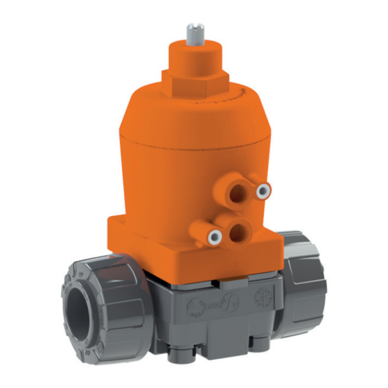
Layout and Function Layout and Function Marking 3.1.1 Name plate MV309 145039 Id No 6 / 15 PN/DN 1407-87345 PP • PTFE • FPM Fig. 1 Nameplate (example) Type ID number Nominal pressure [bar] / Nominal diameter [mm] Materials (valve body, diaphragm, other gaskets) Date of manufacture - Series number Layout Compressed air operated diaphragm valve for shutting off... -
Page 6: Fig
Transport, Storage and Disposal Transport, Storage and Disposal Unpacking and inspection on delivery Disposal 1. Unpack the fitting when received and inspect it for transport Plastic parts can be contaminated by poisonous or radioac- damage. tive media to such an extent that cleaning will not be suffi- cient. -
Page 7: Installation And Connection
Installation and connection Installation and connection Preparing for installation Installing fitting in pipe 5.1.1 Check operating conditions WARNING 1. Ensure the design of the fitting is consistent with the pur- Risk of poisoning and environmental damage from pose intended: medium. –... -
Page 8: Tab
Installation and connection Connecting the drive Fig. 5 Limit switch, type NBB2–V3–E2 R Load Fig. 3 Limit switch, type VCSP closed closed open open Fig. 6 compressed air Fig. 4 Limit switch, type Nj2–V3–N Close valve Open valve closed X1 Valve open open X2 Valve closed MV 309... -
Page 9: Installing Limit Switch
Operation Performing the hydrostatic test 5.4.1 Installing limit switch Only necessary for fittings with limit switches. Pressure test using neutral medium, e.g. water. 1. Pressurize the fitting, ensuring DANGER – Test pressure < permissible system pressure – Test pressure < 1.5 PN Risk of electrocution! –... -
Page 10: Maintenance
Maintenance Maintenance Maintenance WARNING Risk of injury and poisoning due to hazardous media liq- DANGER uids! Use personal protective equipment when carrying out any Risk of electrocution! work on the fitting. All electrical work must be carried out by qualified electri- cians only. -
Page 11: Removing Fitting
Maintenance Replacement parts and return 7.2.1 Removing fitting 1. Ensure that: 1. Have the following information ready to hand when order- – System is empty ing spare parts (→ nameplate). – System has been flushed – Fitting type – System is depressurized –... -
Page 12: Troubleshooting
Troubleshooting Troubleshooting WARNING Risk of injury and poisoning due to hazardous or hot media. Use personal protective equipment when carrying out any work on the fitting. Safely collect the media and dispose of it in accordance with environmental regulations. Consult with the manufacturer regarding faults which are not identified in the following table, or which cannot be traced to the indicated causes. -
Page 13: Appendix
Appendix Appendix Technical specifications Parts Technical data (→ Data sheet). 9.1.1 Mechanical specifications Size Value Process conditions (medium) Pressure and temperature → Data sheet Materials in contact with medium Diaphragm EPDM, FPM, PTFE (EPDM diaphragm, PTFE-coated on medium-side) sealing FPM, EPDM Housing PVC-U, PP, PVDF Materials not in contact with medium... - Page 14 Appendix MV 309 BA-2016.08.04 EN 300 156...
Need help?
Do you have a question about the MV 309 Series and is the answer not in the manual?
Questions and answers