Table of Contents
Advertisement
Quick Links
Ball valve
Operating manual
Version
BA-2022.08.16 EN
Print-No.
302 451
TR MA DE Rev001
Series C 10
STÜBBE GmbH & Co. KG
Hollwieser Straße 5
32602 Vlotho
Germany
Phone: +49 (0) 5733-799-0
Fax: +49 (0) 5733-799-5000
E-mail:
contact@stuebbe.com
Internet:
www.stuebbe.com
Subject to technical modifications.
Read carefully before use.
Save for future use.
Advertisement
Table of Contents

Related Manuals for Stübbe C 10 Series


Summary of Contents for Stübbe C 10 Series
-
Page 1: Fig
Ball valve Operating manual Series C 10 Version BA-2022.08.16 EN STÜBBE GmbH & Co. KG Print-No. 302 451 Hollwieser Straße 5 32602 Vlotho TR MA DE Rev001 Germany Phone: +49 (0) 5733-799-0 Fax: +49 (0) 5733-799-5000 E-mail: contact@stuebbe.com Internet: www.stuebbe.com Subject to technical modifications. -
Page 2: Table Of Contents
Table of contents Table of contents About this document ....... Replacement parts and return . -
Page 3: About This Document
About this document About this document Other applicable documents This manual • is part of the fitting Resistance lists • applies to all series referred to Resistance of materials used to chemicals • describes safe and proper operation during all operating phases www.stuebbe.com/pdf/300051.pdf Target groups... -
Page 4: Safety Instructions
Layout and Function Safety instructions 2.2.2 Obligations of personnel • Observe the instructions on the fitting and keep them leg- ible, e.g. name plate and identification marking for fluid The manufacturer accepts no liability for damages caused connections. by disregarding any of the documentation. •... -
Page 5: Description
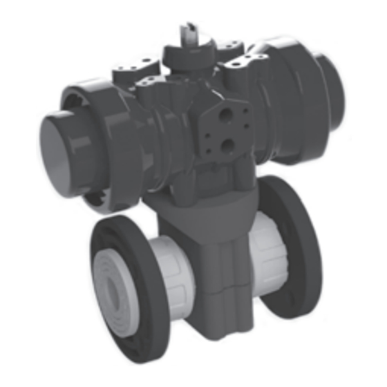
Layout and Function Description 3.3.2 C10 electric drive Manually, electrically or pneumatically driven ball valve for shutting off pipes. • Optional flow direction • Optional installation position – Position electric drive laterally or over the fitting. • Opening angle OPEN/CLOSE 90° •... -
Page 6: Transport, Storage And Disposal
Transport, Storage and Disposal Transport, Storage and Storage Disposal NOTE Material damage due to inappropriate storage! Unpacking and inspection on delivery Store the fitting properly. 1. Unpack the fitting when received and inspect it for trans- 1. Make sure the storage room meets the following condi- portation damage. -
Page 7: Fig
Installation and connection Installation and connection Installing fitting in pipe WARNING Preparations for installation Risk of poisoning and environmental damage from 1. Ensure the design of the fitting is consistent with the pur- medium! pose intended: Leak due to faulty installation. –... -
Page 8: Fig
Installation and connection Drive and limit switch box Connection Limit switch box can only be used with pneumatic drive. 5.5.1 Electrical connection Connection plan (→ Data sheet). DANGER Risk of electrocution! All electrical work must be carried out by qualified electri- cians only. -
Page 9: Unpacking And Inspection On Delivery
Operation Operation 5.5.3 Check sense of rotation of drive 1. Open and close fitting once via drive. 2. Check position of the fitting at the flow indicator: Commissioning – Position indicator along the pipe: Fitting opened Fitting correctly installed and connected Performing the hydrostatic test WARNING Pressure test using neutral medium, e.g. -
Page 10: Maintenance
Maintenance Maintenance 7.2.2 Fixing leaks in the port 1. Removing fitting (→ 7.2.1 Removing fitting, Page 10). 2. Replace ball seals and/or ball. WARNING 3. Install fitting (→ 5.3 Installing fitting in pipe, Page 7 ). Risk of injury and poisoning due to hazardous media liq- 7.2.3 Fix leakage at ball valve stem uids! -
Page 11: Troubleshooting
Troubleshooting Troubleshooting WARNING Risk of injury and poisoning due to hazardous or hot media! Use personal protective equipment when carrying out any work on the fitting. Safely collect the media and dispose of it in accordance with environmental regulations. Consult with the manufacturer regarding faults which are not identified in the following table, or which cannot be traced to the indicated causes. -
Page 12: Appendix
Appendix Appendix Technical specifications Technical data (→ Data sheet). Flange installation Fig. 9 Tightening torques Tightening MD [Nm] for the versions [mm] [mm] Flat sealing Profile seal O-ring ring max. 10 bar max. 16 bar max. 16 bar max. 40 °C Tab. -
Page 13: Replacement Parts
Appendix Replacement parts Fig. 10 Replacement parts Pos. Piece Designation Housing with ball T-handle Circlip pressure piece Radial rotary shaft seal Insert Union nut Radial rotary shaft seal Bracket Coupling Mounting set Electric drive Pneumatic drive Tab. 7 Replacement parts 302 451 BA-2022.08.16 EN C 10...
Need help?
Do you have a question about the C 10 Series and is the answer not in the manual?
Questions and answers