Table of Contents
Advertisement
Quick Links
Ball valve
Operating manual
Version
BA-2022.07.19 EN
Print-No.
300 876
TR MA DE Rev002
Series C 110
STÜBBE GmbH & Co. KG
Hollwieser Straße 5
32602 Vlotho
Germany
Phone: +49 (0) 5733-799-0
Fax: +49 (0) 5733-799-5000
E-mail:
contact@stuebbe.com
Internet:
www.stuebbe.com
We reserve the right to make technical changes.
Read carefully before use.
Save for future use.
Advertisement
Table of Contents

Related Manuals for Stübbe C 110 Series


Summary of Contents for Stübbe C 110 Series
-
Page 1: Fig
Ball valve Operating manual Series C 110 Version BA-2022.07.19 EN STÜBBE GmbH & Co. KG Print-No. 300 876 Hollwieser Straße 5 TR MA DE Rev002 32602 Vlotho Germany Phone: +49 (0) 5733-799-0 Fax: +49 (0) 5733-799-5000 E-mail: contact@stuebbe.com Internet: www.stuebbe.com We reserve the right to make technical changes. -
Page 2: Table Of Contents
Table of contents Table of contents About this document ....... Troubleshooting . -
Page 3: About This Document
About this document About this document Other applicable documents This manual • is part of the fitting Resistance lists • applies to all series referred to Resistance of materials used to chemicals • describes safe and proper operation during all operating phases www.stuebbe.com/pdf/300051.pdf Target groups... -
Page 4: Safety Instructions
Layout and Function Safety instructions 2.2.2 Obligations of personnel • Observe the instructions on the fitting and keep them legi- ble, e.g. type plate, identification marking for fluid connec- The manufacturer accepts no liability for damages caused tions. by disregarding any of the documentation. •... -
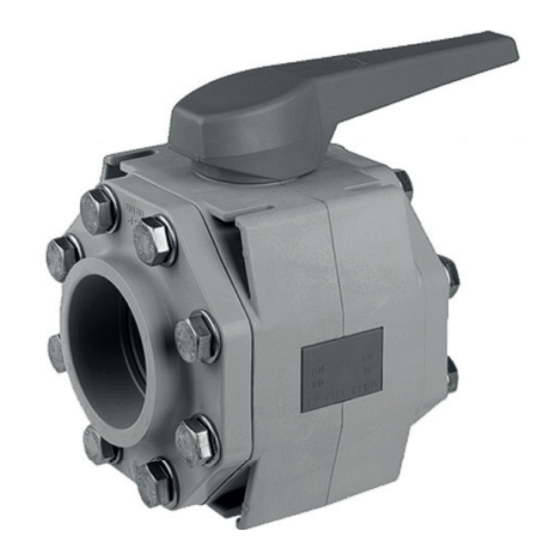
Page 5: Layout
Layout and Function Layout Manually, electrically or pneumatically driven ball valve for shutting off pipes • Optional flow direction • Opening angle OPEN/CLOSE 90° • Optional installation position – Position electric drive laterally or over the fitting. Fig. 2 Layout Housing Hexagon socket screw (MD2) 13 hexagon bolt... -
Page 6: Transport, Storage And Disposal
Transport, Storage and Disposal Transport, Storage and Storage Disposal NOTE Material damage due to inappropriate storage! Unpacking and inspection on delivery Store the fitting properly. 1. Unpack the fitting when received and inspect it for transport 1. Make sure the storage room meets the following condi- damage. -
Page 7: Installation And Connection
Installation and connection Installation and connection Installing fitting in pipe WARNING Preparing for installation Risk of poisoning and environmental damage from 5.1.1 Check operating conditions medium. 1. Ensure the design of the fitting is consistent with the pur- Leak due to faulty installation. pose intended: Installation work on the pipes should only be performed –... -
Page 8: Drive And Limit Switch Box
Installation and connection Drive and limit switch box Limit switch box can only be used with pneumatic drive. Fig. 4 Electric drive Fig. 6 Pneumatic actuator drive with limit switches Electric drive Limit switch box Mounting set Cable gland Housing with ball Pneumatic drive Connection 5.5.1... -
Page 9: Pneumatic Connection
Operation Operation 5.5.2 Pneumatic connection Solenoid pilot valves are available for control of the pneu- matic drive (→ Operating instructions for pilot valve): Commissioning – 3/2-way valve for single-acting drives – 5/2-way valve for double-acting drives Fitting correctly installed and connected CAUTION WARNING Risk of injury from compressed air! -
Page 10: Maintenance
Maintenance Maintenance 7.2.1 Removing fitting 1. Ensure that: – System is empty – System has been flushed WARNING – System is depressurized – System has cooled down Risk of injury and poisoning due to hazardous media liq- – System is secured against being switched back on uids! again Use personal protective equipment when carrying out any... -
Page 11: Troubleshooting
Appendix Troubleshooting WARNING Risk of injury and poisoning due to hazardous or hot media. Use personal protective equipment when carrying out any work on the fitting. Safely collect the media and dispose of it in accordance with environmental regulations. Consult with the manufacturer regarding faults which are not identified in the following table, or which cannot be traced to the indicated causes. -
Page 12: Flange Installation
Appendix Flange installation Description Max. immersion depth flange screws [mm] for the sizes (M16) (M16) (M16) (M16) (M20) Immersion depth Tab. 7 Immersion depth flange screws Tightening torques Description Tightening Size torque [Nm] DN75 Hexagon socket DN90 screws (MD2) DN110 (→...
Need help?
Do you have a question about the C 110 Series and is the answer not in the manual?
Questions and answers