Table of Contents
Advertisement
Available languages
Available languages
Quick Links
Advertisement
Table of Contents

Related Manuals for EuroLite LED IP PAR 12x12W HCL


Summary of Contents for EuroLite LED IP PAR 12x12W HCL
- Page 1 BEDIENUNGSANLEITUNG USER MANUAL LED IP PAR 12x12W HCL LED outdoor color changer Für weiteren Gebrauch aufbewahren! © Copyright Keep this manual for future needs! Nachdruck verboten! Reproduction prohibited!
-
Page 2: Table Of Contents
Diese Bedienungsanleitung gilt für die Artikelnummer 51914187 This user manual is valid for the article number 51914187 Das neueste Update dieser Bedienungsanleitung finden Sie im Internet unter: You can find the latest update of this user manual in the Internet under: www.eurolite.de 2/40 00095287.DOC, Version 1.0... -
Page 3: Einführung
- sich die letzte Version der Anleitung im Internet herunter laden EINFÜHRUNG Wir freuen uns, dass Sie sich für einen EUROLITE LED IP PAR 12x12W HCL entschieden haben. Wenn Sie nachfolgende Hinweise beachten, sind wir sicher, dass Sie lange Zeit Freude an Ihrem Kauf haben werden. - Page 4 Der Aufbau entspricht der Schutzklasse I. Der Netzstecker darf nur an eine Schutzkontakt-Steckdose angeschlossen werden, deren Spannung und Frequenz mit dem Typenschild des Gerätes genau übereinstimmt. Ungeeignete Spannungen und ungeeignete Steckdosen können zur Zerstörung des Gerätes und zu tödlichen Stromschlägen führen. Den Netzstecker immer als letztes einstecken.
-
Page 5: Bestimmungsgemäße Verwendung
BESTIMMUNGSGEMÄßE VERWENDUNG Bei diesem Gerät handelt es sich um einen Architektur-Scheinwerfer, mit dem sich dekorative Lichteffekte erzeugen lassen. Dieses Produkt ist nur für den Anschluss an 100-240 V, 50/60 Hz Wechselspannung zugelassen. Das Gerät ist gegen Strahlwasser geschützt (Schutzart IP 65) und kann deshalb sowohl in Innenräumen als auch im Freien verwendet werden. -
Page 6: Gerätebeschreibung
Beachten Sie bitte, dass eigenmächtige Veränderungen an dem Gerät aus Sicherheitsgründen verboten sind. Der Serienbarcode darf niemals vom Gerät entfernt werden, da ansonsten der Garantieanspruch erlischt. Wird das Gerät anders verwendet als in dieser Bedienungsanleitung beschrieben, kann dies zu Schäden am Produkt führen und der Garantieanspruch erlischt. -
Page 7: Installation
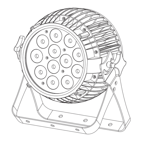
(5) Spannungsversorgungseingang (6) DMX-Eingang (7) Control Board (8) Display (9) Menu-Taste (10) Up-Taste (11) Down-Taste (12) Enter-Taste (13) Fangseilöse (14) DMX-Ausgang (15) Entlüftungsschraube (16) Spannungsversorgungsausgang INSTALLATION Befestigung Vergewissern Sie sich vor der Montage, dass die Montagefläche mindestens die 10-fache Punktbelastung des Eigengewichtes des Gerätes aushalten kann. -
Page 8: Überkopfmontage
Die Montagebügel an der Geräterückseite lassen sich auf die gewünschte Position einstellen. Stellen Sie den Neigungswinkel über die Montagebügel ein und ziehen Sie die Feststellschrauben gut fest. Hinweis: Nachdem Sie die Leuchte am gewünschten Ort installiert haben, ziehen Sie die Schraube an der Unterseite der Montagebügel mit einem Innensechskantschlüssel fest. -
Page 9: Dmx512-Ansteuerung
BRANDGEFAHR! Achten Sie bei der Installation des Gerätes bitte darauf, dass sich im Abstand von mind. 0,5 m keine leicht entflammbaren Materialien (Deko, etc.) befinden. Befestigen Sie das Gerät über einen geeigneten Haken an Ihrem Traversensystem. Sichern Sie das Gerät bei Überkopfmontage immer mit einem geeigneten Sicherungsseil. Es dürfen nur Sicherungsseile und Schnellverbindungsglieder gemäß... -
Page 10: Master/Slave-Betrieb
Belegung der XLR-Verbindung: Wenn Sie Controller mit dieser XLR-Belegung verwenden, können Sie den DMX-Ausgang des Controllers direkt mit dem DMX-Eingang des ersten Gerätes der DMX-Kette verbinden. Sollen DMX-Controller mit anderen XLR-Ausgängen angeschlossen werden, müssen Adapterkabel verwendet werden. Aufbau einer seriellen DMX-Kette: Schließen Sie den DMX-Ausgang des ersten Gerätes der Kette an den DMX-Eingang des nächsten Gerätes an. -
Page 11: Anschluss Zwischen Geräten
Das Gerät hat zwei Betriebsarten. Es kann entweder im Standalone-Modus oder im DMX-gesteuerten Modus über einen handelsüblichen DMX-Controller betrieben werden. Standalone-Modus Der LED IP PAR 12x12W HCL lässt sich im Standalone-Betrieb ohne DMX-Controller einsetzen. Trennen Sie dazu der LED IP PAR 12x12W HCL vom DMX-Controller. 11/40... -
Page 12: Control Board
Control Board Das Control Board bietet mehrere Möglichkeiten: so lassen sich z. B. die DMX-Startadresse eingeben, das vorprogrammierte Programm abspielen oder ein Reset durchführen. Drücken Sie die Menu-Taste, so dass sich das Display einschaltet. Über die Up-/ Down Taste können Sie sich im Hauptmenü... - Page 13 Display-Abschaltung DISY ON – immer an 2MIN 2MIN – Abschaltung nach 2 Minuten Tastensperre YES – Tastensperre nach 2 Minuten. Um LOCK YES/NO die Tastensperre aufzuheben, eine beliebige Taste für 10 Sekunden gedrückt halten. 0-255 0-255 0-255 CT01 – Individuelle Kunden-Farbeinstellung CTST CT10 0-255...
-
Page 14: Dmx-Modus
Bitte vergewissern Sie sich, dass sich die Steuerkanäle nicht mit anderen Geräten überlappen, damit der LED IP PAR 12x12W HCL korrekt und unabhängig von anderen Geräten in der DMX-Kette funktioniert. Werden mehrere LED IP PAR 12x12W HCL auf eine Adresse definiert, arbeiten sie synchron. -
Page 15: Dmx-Protokoll
DMX-Protokoll 4-Kanal-Modus Steuerkanal 1 - Rot Decimal Hexad. Percentage S/F Eigenschaft 0 255 00 FF 0% 100% Rot (0=aus, 255=100% rot) Steuerkanal 2 - Grün Decimal Hexad. Percentage S/F Eigenschaft 0 255 00 FF 0% 100% Grün (0=aus, 255=100% grün) Steuerkanal 3 - Blau Decimal Hexad. - Page 16 131 131 83 83 51% 51% Gelb 132 170 84 AA 52% 67% Rot 100% / Grün abnehmend / Blau 0% / Weiß 0% 171 171 AB AB 67% 67% 172 210 AC D2 67% 82% Rot 100% / Grün 0% / Blau zunehmend / Weiß 0% 211 211 D3 D3 83% 83% Magenta...
- Page 17 Steuerkanal 3 - Grün Decimal Hexad. Percentage S/F Eigenschaft 0 255 00 FF 0% 100% Grün (0=aus, 255=100% grün) Steuerkanal 4 - Blau Decimal Hexad. Percentage S/F Eigenschaft 0 255 00 FF 0% 100% Blau (0=aus, 255=100% blau) Steuerkanal 5 - Amber Decimal Hexad.
- Page 18 Steuerkanal 7 - UV Decimal Hexad. Percentage S/F Eigenschaft 0 255 00 FF 0% 100% UV (0=aus, 255=100% UV) Steuerkanal 8 - Strobe Decimal Hexad. Percentage S/F Eigenschaft 00 05 0% 2% Keine Funktion 6 20 06 14 2% 8% Strobe-Effekt (asynchron) mit zunehmender Geschwindigkeit 21 60 15 3C...
- Page 19 Steuerkanal 5 - Amber Decimal Hexad. Percentage S/F Eigenschaft 0 255 00 FF 0% 100% Amber (0=aus, 255=100% amber) Steuerkanal 6 - Weiß Decimal Hexad. Percentage S/F Eigenschaft 0 255 00 FF 0% 100% Weiß (0=aus, 255=100% weiß) Steuerkanal 7 - UV Decimal Hexad.
- Page 20 136 140 88 8C 53% 55% 141 145 8D 91 55% 57% Gelb 146 150 92 96 57% 59% Pink 151 155 97 9B 59% 61% Cyan 156 160 9C A0 61% 63% Orange 161 165 A1 A5 63% 65% Violett 166 170 A6 AA 65% 67% Goldgelb...
-
Page 21: Reinigung Und Wartung
REINIGUNG UND WARTUNG LEBENSGEFAHR! Vor Wartungsarbeiten unbedingt allpolig vom Netz trennen! Das Gerät sollte regelmäßig von Verunreinigungen wie Staub usw. gereinigt werden. Verwenden Sie zur Reinigung ein fusselfreies, angefeuchtetes Tuch. Auf keinen Fall Alkohol oder irgendwelche Lösungsmittel zur Reinigung verwenden! Im Geräteinneren befinden sich keine zu wartenden Teile. -
Page 22: Introduction
- download the latest version of the user manual from the Internet INTRODUCTION Thank you for having chosen a EUROLITE LED IP PAR 12x12W HCL. If you follow the instructions given in this manual, we are sure that you will enjoy this device for a long period of time. -
Page 23: Operating Determinations
Always plug in the power plug last. The power plug must always be inserted without force. Make sure that the plug is tightly connected with the outlet. Never let the power-cord come into contact with other cables! Handle the power-cord and all connections with the mains with particular caution! Never touch them with wet hands, as this could lead to mortal electrical shock. - Page 24 The maximum relative humidity is 100 % with an ambient temperature of 25° C. This device must only be operated in an altitude between -20 and 2000 m over NN. This device is designed for professional use. Do not shake the device. Avoid brute force when installing or operating the device. When choosing the installation-spot, please make sure that the device is not exposed to extreme heat, moisture or dust.
-
Page 25: Description Of The Device
DESCRIPTION OF THE DEVICE Features Ultra-flexible LED architectural spot with 12 W hexacolor LEDs • Equipped with 12 x 6in1 HCL LED in the colors red, green, blue, amber, white and UV • Flicker-free projection • 4, 5, 6, 7, 9 or 12 DMX channels selectable •... -
Page 26: Installation
(5) Power input (6) DMX-Input (7) Control Board (8) Display (9) Menu button (10) Up button (11) Down button (12) Enter button (13) Safety eyelet (14) DMX output (15) Vent screw (16) Power output INSTALLATION Attachment Before attaching the device, make sure that the installation area can hold a minimum point load of 10 times the device's weight. -
Page 27: Overhead Rigging
Attention: After mounting the LED effect in the desired location, be sure to tighten the screw on the bottom of the mounting brackets with a hexagonal key. This prevents a possible slipping of the device. Overhead rigging DANGER TO LIFE! Please consider the EN 60598-2-17and the respective national standards during the installation! The installation must only be carried out by an authorized dealer! The installation of the device has to be built and constructed in a way that it can hold 10 times the weight for... -
Page 28: Dmx512 Control
For overhead use, always install an appropriate safety bond. You must only use safety bonds and quick links complying with DIN 56927, shackles complying with DIN EN 1677-1 and BGV C1 carbines. The safety bonds, quick links, shackles and the carbines must be sufficiently dimensioned and used correctly in accordance with the latest industrial safety regulations (e. -
Page 29: Master/Slave Operation
Caution: At the last fixture, the DMX cable has to be terminated. Plug the terminator with a 120 resistor between Signal (–) and Signal (+) in the DMX output of the last fixture. The DMX connection can be made via DMX adapters or special DMX connection cables. The important thing about this is that the connection is always sufficiently isolated against humidity. -
Page 30: Operation
The device has two operating modes. It can be operated in stand-alone mode or in DMX-controlled mode via any standard DMX controller. Stand-alone Mode In the stand-alone mode, the LED IP PAR 12x12W HCL can be used without DMX-controller. Disconnect the LED IP PAR 12x12W HCL from the DMX-controller. 30/40... -
Page 31: Control Board
Control Board The Control Board offers several features: you can simply set the starting address, run the pre-programmed program or make a reset. The main menu is accessed by pressing Menu until the display is lit. Browse through the menu by pressing Up or Down. - Page 32 Display shutoff ON – permanent on DISY 2MIN - shut off the display after 2 2MIN minutes Keylock LOCK YES/NO YES – Keylock after 2 minutes. To unlock press any key for 10 seconds. 0-255 0-255 0-255 CT01 – Individual customer color setting CTST CT10 0-255...
-
Page 33: Dmx Mode
The Control Board allows you to assign the DMX fixture address, which is defined as the first channel from which the LED IP PAR 12x12W HCL will respond to the controller. Please, be sure that you don’t have any overlapping channels in order to control each LED IP PAR 12x12W HCL correctly and independently from any other fixture on the DMX-chain. -
Page 34: Dmx Protocol
DMX Protocol 4 channel mode Control-channel 1 - Red Decimal Hexad. Percentage Feature 0 255 00 FF 0% 100% Red (0=off, 255=100% red) Control-channel 2 - Green Decimal Hexad. Percentage S/F Feature 0 255 00 FF 0% 100% Green (0=off, 255=100% green) Control-channel 3 - Blue Decimal Hexad. - Page 35 131 131 83 83 51% 51% Yellow 132 170 84 AA 52% 67% Red 100% / green decreasing / blue 0% / white 0% 171 171 AB AB 67% 67% 172 210 AC D2 67% 82% Red 100% / green 0% / blue increasing / white 0% 211 211 D3 D3 83% 83% Magenta...
- Page 36 Control-channel 3 - Green Decimal Hexad. Percentage S/F Feature 0 255 00 FF 0% 100% Green (0=off, 255=100% green) Control-channel 4 - Blue Decimal Hexad. Percentage S/F Feature 0 255 00 FF 0% 100% Blue (0=off, 255=100% blue) Control-channel 5 - Amber Decimal Hexad.
- Page 37 Control-channel 7 - UV Decimal Hexad. Percentage S/F Feature 0 255 00 FF 0% 100% UV (0=off, 255=100% UV) Control-channel 8 - Strobe Decimal Hexad. Percentage S/F Feature 00 05 0% 2% No function 6 20 06 14 2% 8% Strobe-effect (asynchron) with increasing speed 21 60 15 3C...
- Page 38 Control-channel 5 - Amber Decimal Hexad. Percentage S/F Feature 0 255 00 FF 0% 100% Amber (0=off, 255=100% amber) Control-channel 6 - White Decimal Hexad. Percentage S/F Feature 0 255 00 FF 0% 100% White (0=off, 255=100% white) Control-channel 7 - UV Decimal Hexad.
- Page 39 136 140 88 8C 53% 55% 141 145 8D 91 55% 57% Yellow 146 150 92 96 57% 59% Pink 151 155 97 9B 59% 61% Cyan 156 160 9C A0 61% 63% Orange 161 165 A1 A5 63% 65% Violet 166 170 A6 AA 65% 67% Golden...
-
Page 40: Cleaning And Maintenance
CLEANING AND MAINTENANCE DANGER TO LIFE! Disconnect from mains before starting maintenance operation! We recommend a frequent cleaning of the device. Please use a soft lint-free and moistened cloth. Never use alcohol or solvents! There are no serviceable parts inside the device. Maintenance and service operations are only to be carried out by authorized dealers.
Need help?
Do you have a question about the LED IP PAR 12x12W HCL and is the answer not in the manual?
Questions and answers