Table of Contents

Related Manuals for Avidsen ELIA


Summary of Contents for Avidsen ELIA
- Page 1 VIDEOPHONE - 2-WIRE ÉLIA Ref.112290 MAYA Ref.112291 100m Eco- Weather- 2-wire Range friendly resistant connection POLARITY PROTECT Night Screen Touch Number French vision size buttons of melodies Design www.avidsen.com...
- Page 2 CONTENTS...
-
Page 3: Table Of Contents
A - SAFETY D - USING THE PRODUCT INSTRUCTIONS 1 - INTRODUCTION 1 - IDENTIFY AND SPEAK TO THE VISITOR 2 - MAINTENANCE AND CLEANING 2 - ACTIVATE THE INTERCOM PANEL FROM THE MONITOR 3 - RECYCLING 3 - OPENING AN ELECTRIC LOCK AND AN AUTOMATIC CONTROL SYSTEM PRODUCT (OPTIONAL) -
Page 5: A - Safety Instructions
A - SAFETY INSTRUCTIONS (insulating screw joints, soldered joints, etc.) 1 - INTRODUCTION 3 - RECYCLING This video intercom system pairs two modules: a This symbol means that devices no longer receiver-monitor and an easy-to-install and use in use should not be disposed of with intercom panel. -
Page 6: B - Product Description
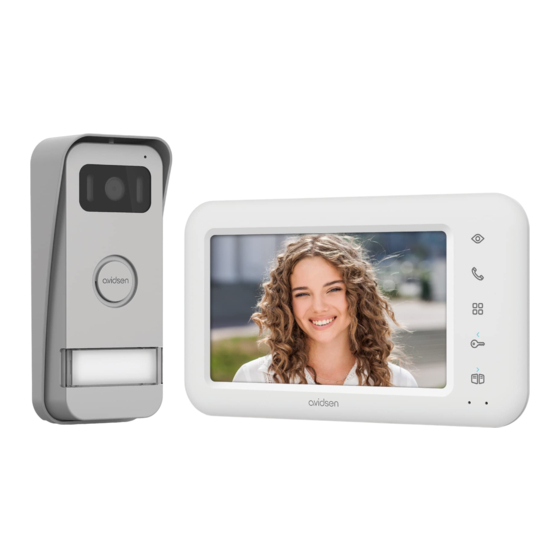
B - PRODUCT DESCRIPTION 1 - CONTENTS OF THE KIT Monitor Screws (4 for the monitor, 3 for the intercom panel) Intercom panel Allen key Monitor wall bracket Mains adaptor Dowels (4 for the monitor, 3 for the intercom panel) Snap-on terminal block for the intercom panel 2 - MONITOR 7"... -
Page 7: Intercom Panel
B - PRODUCT DESCRIPTION 3 - INTERCOM PANEL Protective hood Microphone Lens Infrared lighting Loudspeaker Call button Name label Detachable connection terminals 4 - WALL BRACKET The monitor is designed to be fixed to the wall. A wall bracket and the necessary fasteners are included. 5 - MAINS ADAPTER A 230 Vac 50 Hz/17 Vdc 1.5 A mains adapter for powering the monitor is included in the kit. -
Page 8: C - Installation
C - INSTALLATION The recommended installation height for the intercom panel is about 160 cm from the ground and 150 cm from the floor for the indoor unit. 50cm 70° 160cm 150cm NOTE: For obvious safety reasons, the connections must only be made after shutting off the power supply. 1 - INTERCOM PANEL INSTALLATION Attach the intercom panel hood to your support using the screws and wall plugs suited to the support (the screws and plugs supplied are suitable for solid walls). - Page 9 C - INSTALLATION After making the connections on the intercom panel (see the connections paragraph), put the intercom panel into the hood. Then screw the intercom panel to the hood with the screw provided. Put on the name label.
-
Page 10: Installing The Monitor
C - INSTALLATION 2 - INSTALLING THE MONITOR Attach the wall mount to the wall using the screws and wall plugs suited to the support (the screws and plugs supplied are suitable for solid walls). After connecting the monitor (refer to the “connections” paragraph), fit the monitor onto its support. 3 - CONNECTIONS •... -
Page 11: Connection Between The Monitor And The Intercom Panel
C - INSTALLATION Cable length Section to use 0 to 50 m 0.75 mm 50 m to 100 m 1.5 mm Between the intercom panel and an electric strike plate (not included) Use a 12V/1.1A maximum electric strike plate with mechanical memory. For the connection between the intercom panel and the door release, use a cable of this kind: Cable length Section to use... -
Page 12: D - Using The Product
D - USING THE PRODUCT 1 - IDENTIFY AND SPEAK TO THE VISITOR AUTOMATIC CONTROL SYSTEM (OPTIONAL) The visitor presses the intercom panel’s call button: If the device is equipped with an electric lock and/ or an automatic control system (see “Connection” paragraph), press the button (for the lock) or the button (for the automatic control system) to let a... -
Page 13: Monitor Settings
D - USING THE PRODUCT 4 - MONITOR SETTINGS With the screen on, press the button to display the following screen: Browse the sub-menus by pressing the buttons CON . COL . CALL . INCOME . RING . • BRT: Brightness: press the buttons to decrease or increase the brightness level of the image. -
Page 14: E - Technical And Legal Information
E - TECHNICAL AND LEGAL INFORMATION 1 - TECHNICAL CHARACTERISTICS MONITOR Ultra-flat 7" colour LCD Screen PAL/NTSC Video standard 800 x 480 Resolution with 230 VAC 50 Hz / 17 VDC 1.5 A Power supply mains adapter included Short circuit and reverse polarity protection Protection 2-wire Transmission system (audio and video) -
Page 15: Warranty
E - TECHNICAL AND LEGAL INFORMATION Avidsen undertakes to keep a stock of spare parts 2 - WARRANTY for this product throughout the contractual warranty period. • This product is guaranteed for parts and labour for 3 years from the date of purchase. Proof of purchase must be retained for the duration of the warranty period. - Page 16 19 Avenue Marcel Dassault ZAC des Deux Lions - 37200 Tours - France Photographs and illustrations non-binding/©AdobeStock.com/© Avidsen France 2023...
Need help?
Do you have a question about the ELIA and is the answer not in the manual?
Questions and answers