iDataLink maestro Rr Install Manual
Hide thumbs
Also See for maestro Rr:
- Install manual (1403 pages) ,
- How to use manual (201 pages) ,
- Manual (106 pages)
Table of Contents
Advertisement
Quick Links
SELECT VEHICLE
PRINT PAGES NEEDED
HOW TO USE THIS INSTALL GUIDE
1
Open the Bookmarks menu and find your vehicle OR scroll
down until you find the install guide for your vehicle.
2
Print only the pages for your vehicle using the advanced
options in the Print menu.
3
Install your Maestro RR according to the guide for your vehicle.
Pressing the printer icon or "quick printing" this document will print
NOTICE: Automotive Data Solutions Inc. (ADS) recommends having this installation performed by a certifi ed technician. Logos and trademarks used here in
are the properties of their respective owners.
WARNING
all of the guides in this compilation.
Advertisement
Table of Contents

Related Manuals for iDataLink maestro Rr


Summary of Contents for iDataLink maestro Rr
- Page 1 Print only the pages for your vehicle using the advanced options in the Print menu. Install your Maestro RR according to the guide for your vehicle. WARNING Pressing the printer icon or “quick printing” this document will print all of the guides in this compilation.
-
Page 2: Install Guide
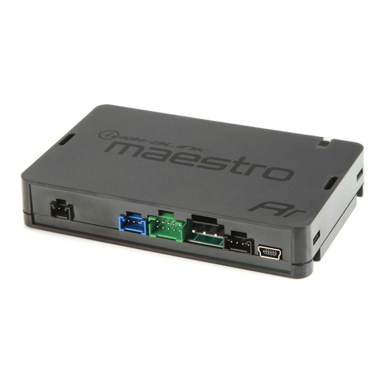
PRODUCTS REQUIRED PROGRAMMED FIRMWARE: FO2-RR-DS iDatalink Maestro RR Radio Replacement Interface iDatalink Maestro K150 Dash Kit NOTICE: Automotive Data Solutions Inc. (ADS) recommends having this installation performed by a certified technician. Logos and trademarks used here in are the properties of their respective owners. -
Page 3: Need Help
Ford F150 with MyFord 4 inch screen 2013-2014 WELCOME ADDITIONAL INFORMATION AND ACCESSORIES Congratulations on the purchase of your iDatalink Maestro RR Radio replacement solution. You are HEAD UNIT ADAPTER: now a few simple steps away from ACC-HU-PIO1, SON1, KEN1, KEN2, ALP1 enjoying your new car radio with enhanced features. -
Page 4: Installation Instructions
It will be relocated to the K150 dash kit. (1.8) Fig. 1.7 Fig. 1.8 STEP 8 • Remove (2) 7mm screws from pocket on top dash, and remove pocket lifting from the forward edge fi rst. (1.9) Fig. 1.9 Automotive Data Solutions Inc. © 2023 FO2-RR-DS-(HRR-K150)-EN maestro.idatalink.com... - Page 5 • Plug the Data cable to the data port of the aftermarket radio (labeled iDatalink). Fig. 2.3 • Insert the Audio cable into the iDatalink 3.5 mm audio MAKE CONNECTIONS jack of the aftermarket radio (If there is no iDatalink audio input, connect to AUX).
-
Page 6: Wiring Diagram
MIC 2 N.C. N.C. WHITE/BLUE - 53 WHITE - 54 STEP 5 YELLOW BLACK OBDII CONNECTOR MAESTRO RR MODULE WHITE/BLUE - 6 WHITE - 14 10 11 12 13 15 16 AMP TURN ON AMP TURN ON HRR-F150 T-HARNESS GEN 1... -
Page 7: Radio Wire Reference Chart
Wire Color on Adapter Kenwood Radio Wire Description E-Brake LtGreen LtGreen Reverse Light* Purple/White Purple/White Steering Wheel Controls (DATA) Blue/Yellow * Reverse light wire: Only connect to radio or module damage will occur. Automotive Data Solutions Inc. © 2023 FO2-RR-DS-(HRR-K150)-EN maestro.idatalink.com... -
Page 8: Module Diagnostics
Problem detected. Consult troubleshooting table. • 1 GREEN flash After radio boots up : Normal operation. • 3 GREEN flashes Bluetooth is activated. Turns off after one minute: Normal operation. • • Normal operation (inactive). Automotive Data Solutions Inc. © 2023 FO2-RR-DS-(HRR-K150)-EN maestro.idatalink.com... -
Page 9: Troubleshooting Table
The light on the Maestro is blinking RED TWICE and the radio IS turning on. Ensure the 4-pin data cable is connected between the radio and the RR, and that it is plugged into the black port on the Maestro RR. The red and blue ports on the RR should be empty. - Page 10 Print only the pages for your vehicle using the advanced options in the Print menu. Install your Maestro RR according to the guide for your vehicle. WARNING Pressing the printer icon or “quick printing” this document will print all of the guides in this compilation.
- Page 11 PRODUCTS REQUIRED PROGRAMMED FIRMWARE: FO2-RR-AS iDatalink Maestro RR Radio Replacement Interface iDatalink Maestro K150 Dash Kit NOTICE: Automotive Data Solutions Inc. (ADS) recommends having this installation performed by a certified technician. Logos and trademarks used here in are the properties of their respective owners.
- Page 12 Ford F150 with MyFord 4 inch screen 2013-2014 WELCOME ADDITIONAL INFORMATION AND ACCESSORIES Congratulations on the purchase of your iDatalink Maestro RR Radio replacement solution. You are HEAD UNIT ADAPTER: now a few simple steps away from ACC-HU-PIO1, SON1, KEN1, KEN2, ALP1 enjoying your new car radio with enhanced features.
- Page 13 Remove both. (1.7) STEP 7 • Remove the traction control button from the factory radio bezel; It will be relocated to the K150 dash kit. (1.8) Fig. 1.7 Fig. 1.8 Fig. 1.9 Automotive Data Solutions Inc. © 2023 FO2-RR-AS-(HRR-K150)-EN maestro.idatalink.com...
- Page 14 STEP 4 Fig. 2.1 Fig. 2.2 • Connect all the harnesses to the Maestro RR module. • If Maestro module is labeled RR (256) 1.0: Use of GEN 1 red 4-pin cable and adapters is required. • All other RR Modules listed RR (512) 2-4 will use GEN 2 red 4-pin cable.
- Page 15 STEP 5 FROM VEHICLE GEN 2 GEN 2 BLACK N.C. STEP 4 AMP TURN ON AMP TURN ON N.C. MAESTRO RR MODULE HRR-F150 T-HARNESS NOT REQUIRED MIC 1 MIC 1 MIC 2 MIC 2 GEN 1 GEN 1 DATA CABLE...
- Page 16 Wire Description Refer to camera/ Green/Red E-Brake LtGreen LtGreen radio manual Refer to camera/ Reverse Light* Purple/White Purple/White Green/White radio manual Steering Wheel Controls (DATA) Blue/Yellow Blue/Yellow Steering Wheel Controls (DATA) Blue/Yellow Blue/Yellow Automotive Data Solutions Inc. © 2023 FO2-RR-AS-(HRR-K150)-EN maestro.idatalink.com...
- Page 17 Flash module using Weblink Desktop and log in. Do NOT use DEMO MODE. • 1 GREEN flash After radio boots up : Normal operation. • 3 GREEN flashes Bluetooth is activated. Turns off after one minute: Normal operation. • • Normal operation (inactive). Automotive Data Solutions Inc. © 2023 FO2-RR-AS-(HRR-K150)-EN maestro.idatalink.com...
- Page 18 During the module programming, ensure you selected K150 as the accessory and not FO2. MAESTRO RR RESET PROCEDURE: Turn the key to the OFF position, then disconnect all connectors from the module. Press and hold the module’s programming button and connect all the connectors back to the module. Wait, the module’s LED will fl ash RED rapidly (this may take up to 10 seconds).
Need help?
Do you have a question about the maestro Rr and is the answer not in the manual?
Questions and answers