Table of Contents
Advertisement
Available languages
Available languages
Quick Links
Advertisement
Table of Contents

Related Manuals for universalblue MISTRAL 3052


Summary of Contents for universalblue MISTRAL 3052
-
Page 2: Table Of Contents
Ventilador de techo Ceiling fan ÍNDICE ESPAÑOL INSTRUCCIONES DE SEGURIDAD ..........3 CARACTERÍSTICAS DEL PRODUCTO ..........5 MONTAJE E INSTALACIÓN ............7 FUNCIONAMIENTO ..............20 LIMPIEZA Y MANTENIMIENTO ........... 22 SERVICIO POSTVENTA ..............22 INFORMACION INHERENTE AL MEDIOAMBIENTE ....23 ENGLISH 1. -
Page 3: Español
ESPAÑOL Felicidades por haber adquirido este producto. recomendamos dedique algún tiempo leer cuidadosamente este Manual de Instrucciones / Instalación con el fin de hacer un buen uso del mismo. Lea cuidadosamente todas las instrucciones de seguridad antes de utilizar el aparato y conserve este Manual de Instrucciones / Instalación para poder consultarlo en el futuro. - Page 4 El ventilador debe colgarse de una estructura capaz de soportar un peso de al menos 45 kg. La fijación debe ser capaz de soportar el peso del ventilador en movimiento sin que se mueva. Asegúrese de que en el lugar de instalación las aspas no entren en contacto con cualquier objeto.
-
Page 5: Características Del Producto
No introduzca ningún objeto en las aspas del ventilador mientras están girando. Esto puede dañarlas y alterar el equilibrio del ventilador, incluso podría llegar a tumbarlo. Después de que el ventilador esté completamente instalado asegúrese de que todas las fijaciones están bien sujetas para evitar cualquier tambaleo o caída de la máquina. -
Page 7: Montaje E Instalación
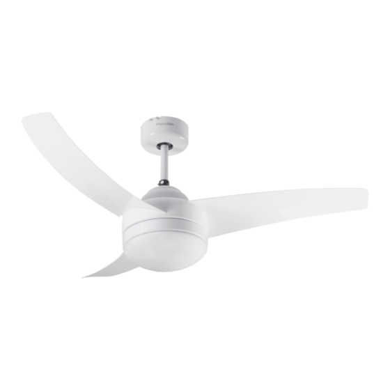
CARACTERÍSTICAS UVT1300-20 Ventilador de techo blanco Dimensión 42” (106 cm) Potencia máxima: 60 W 3 aspas Material aspas: Plástico Con control remoto Con porta lámparas (2; Bombillas no incluidas) Con temporizador Con accesorios para facilitar el montaje CARACTERÍSTICAS UVT1301-20 Ventilador de techo blanco Dimensión 52”... - Page 8 DONDE INSTALAR Asegúrese que el lugar en el que se vaya a instalar el ventilador sea bastante amplio, ya que esto permitirá un mejor flujo del aire y que las aspas del mismo no entren en contacto con cualquier objeto, espacio mínimo de 0,6m por cada lado.
- Page 9 ángulo de inclinación no supere los 25º. Se ha adquirido un modelo fijo no podrá ser instalado en techos inclinados. Nuestros ventiladores no están diseñados para instalar en pladur o falso techo, pues estos materiales podrían no soportar los 45Kg. Nota: Los tornillos de fijación (incluidos) están diseñados para su uso con el ventilador y ser fijados en vigas de madera.
- Page 10 PASO A PASO Nota: Las imágenes son orientativas y sólo deben ser utilizadas como apoyo a la instalación. Montaje de las aspas (A) 1. Retire los tornillos de la bolsa de accesorios o desenrrosquelos de la parte inferior de la estructura de la lámpara (B). Dependiendo del modelo adquirido cada aspa podrá...
- Page 11 Montaje del soporte bombillas (C) 3. Desenrosque los 3 tornillos que hay en la parte inferior de la estructura de la lámpara (B). Dependiendo del modelo adquirido, los 3 tornillos estarán dispuestos como la imagen de abajo (3) o bien en forma triangular en el centro de la estructura del ventilador.
- Page 12 6. Coloque las bombillas (no incluidas) El ventilador utiliza bombillas E27 de 60W. Cuando se coloque las bombillas asegúrese que no toquen la cubierta de la lámpara ni el soporte de la lámpara. 7. Coloque el cristal (E) con mucho cuidado pues se trata de una pieza muy frágil.
- Page 13 (C). Haga coincidir las ranuras con los pequeños resaltes que tiene el soporte bombilla (C). 8. Quite el tornillo superior del cuerpo y coloque la barra de sujeción (E) junto con el florón superior (D). Una vez ajustadas las partes fije la barra de sujeción (E) con la estructura de la lámpara (B) con el tornillo anterior nuevamente.
- Page 14 Montaje al techo 9. Desenrosque los tornillos laterales del soporte del receptor (G) tal y como se indica en la imagen de abajo. 10. Realice los agujeros pertinentes en el techo para poder anclar el soporte del receptor (G) al techo. Tenga en cuenta las anotaciones previamente enumeradas que hacen referencia a los tipos de techo.
- Page 15 12. Coloque el receptor de señal del mando a distancia (I) en la posición correcta entre el soporte del receptor (G) y el ventilador. Los cables deben quedar en el lado de la regleta del receptor (G).
- Page 16 13. En el receptor de señal del mando a distancia (I) verá 2 cables en un lateral del receptor y 3 cables salientes del lateral contrario, tal y como muestra la imagen orientativa inferior: 14. Los 3 cables salientes del receptor (I) (banco, negro y azul) deberán empalmarse con los cables salientes de la barra de sujeción (E) .
- Page 17 sujección (E) , se deben introducir por la misma sujeción de la regleta (señalizada con el símbolo de conexión a tierra). 17. Los cables salientes de la pared (red eléctrica del hogar) deberán conectarse utilizando el lado opuesto de la regleta. Empalme los cables a través de la regleta siguiendo los colores de los cables previamente colocados.
- Page 18 KIT DE EQUILIBRIO DE ASPAS Junto con el producto adquirido encontrará un kit suministrado para evitar que las aspas se muevan desequilibradas. El ventilador puede tambalearse durante su funcionamiento debido a una irregularidad en las aspas o en el soporte de las mismas. Además, una instalación incorrecta o un ángulo torcido pueden causar algún problema adicional.
- Page 19 Mirando al ventilador desde abajo, compruebe y asegúrese de que ningún soporte de aspas esté torcido de manera que ninguna de las aspas esté fuera de su posición. En ese caso, se puede corregir doblando muy suavemente el soporte del aspa para devolverlo de nuevo a su posición.
-
Page 20: Funcionamiento
INFORMACIÓN SOBRE LAS BOMBILLAS Este producto se suministra sin bombillas. Puede incorporar dos bombillas de rosca E27 con una potencia máxima de 60W (tipo incandescente). Compruebe la equivalencia de la potencia de la bombilla LED que vaya adquirir con la potencia incandescente. - Page 21 Para encender el ventilador presione el botón low/Med/Hi en base al flujo de ire deseado. LIGHT ON / OFF: Presione y suelte para encender o apagar la luz. STOP: Para apagar el ventilador HI: Ventilador girando a la máxima velocidad.
-
Page 22: Limpieza Y Mantenimiento
LIMPIEZA Y MANTENIMIENTO Este producto no requiere un gran mantenimiento. Para limpiarlo, por favor siga las siguientes instrucciones: Desenchufe primero el ventilador y espere hasta que se detenga completamente. Use sólo un paño húmedo suave. No utilice productos de limpieza abrasivos. ... -
Page 23: Informacion Inherente Al Medioambiente
Para hacer uso de la garantía acuda al centro donde compró este producto o bien contacte con nosotros de cualquiera de las siguientes formas: o A través del email sat@universalblue.es adjuntando la factura de compra e indicando sus datos de contacto y brevemente qué problema presenta su termo eléctrico. - Page 24 sino que se debe llevar a los centros de recogida diferenciada de desperdicios eléctricos y electrónicos o bien entregar al vendedor en el momento de comprar un nuevo aparato. La adecuada recogida de este aparato contribuye a evitar posibles repercusiones negativas para el ambiente o la salud de las personas.
- Page 25 Puedes descargar este manual en nuestra página web: www.universalblue.es *Universal for Engineering Industries Spain, S.L. se reserva el derecho de hacer cualquier cambio en las especificaciones y características de los productos sin previo aviso, debido a la mejora continua de los productos. Las imágenes aquí mostradas son orientativas, por lo que puede haber pequeñas diferencias entre las imágenes y el producto que haya...
-
Page 26: English
ENGLISH Congratulations on your purchase of this product. We recommend that you take some time to carefully read this Instruction / Installation Manual in order to make good use of it. Carefully read all safety instructions before using the device and keep this Instruction / Installation Manual for future reference. - Page 27 fixture must be able to support the weight of the moving fan without moving. Make sure that at the installation site the blades do not come into contact with any objects. Always leave a minimum clearance of 150 mm from the tip of the blades to the wall or ceiling.
-
Page 28: Product Features
Due to the natural motion of the fan, some connections become loose. Check connections at least twice a year, and if they are loose, tighten them. 2. PRODUCT FEATURES The contents of the package will contain the following items, in addition to this manual and the product warranty. -
Page 30: Assembly And Installation
FEATURES UVT1300-20 White ceiling fan Dimension 42” (106 cm) Maximum power: 60 W 3 blades Blades’ Material: Plastic With remote control With lamp holder (2; bulbs not included) With timer With accessories for easy assembly FEATURES UVT1301-20 White ceiling fan Dimension 52”... - Page 31 WHERE TO INSTALL Make sure that the place where the fan is going to be installed is quite wide, as this will allow a better air flow and that the fan blades do not come into contact with any object, minimum space of 0.6m on each side.
- Page 32 Note: Fastening screws (included) are designed for use with the fan and are fastened to wooden beams. If the installation is carried out on a different material, it is advisable to use the appropriate fixing screws for that material (these screws are not supplied with this equipment).
- Page 33 Mounting the bulb holder (C) Unscrew the 3 screws at the bottom of the lamp structure (B). Depending on the model purchased, the 3 screws will be...
- Page 34 arranged as shown below (3) or in a triangular shape in the centre of the fan frame. Place the bulb holder structure (C) matching the holes in the lamp structure (B) and return the screws to their original position. Make the electrical connection between the lamp structure (B) and the bulb holder structure (C).
- Page 35 Place the bulbs (not included). The fan uses 60W E27 bulbs. When placing the bulbs, make sure they do not touch the lamp cover or lamp holder. Place the glass (F) very carefully as it is a very fragile piece. The glass (F) is screwed into the bulb holder structure (C).
- Page 36 Unscrew the screw allocated in the upper part of the lamp structure (B) and place the support rod (E) together with the upper canopy (D). Fix the lamp structure (B) with the support rod (E) using the screw removed previously. The connecting cables should be run through the inside of the support rod (E) to the opposite end.
- Page 37 Place the remote control signal receiver (I) in the correct position between the receiver bracket (G) and the fan. The cables should be on the side of the receiver strip (G). On the signal receptor (I) you will see 2 cables on one side of the receiver and 3 cables protruding from the opposite side, as shown in the image below:...
- Page 38 The 3 cables coming out of the signal receptor (I) (white, black and blue) must be connected with the cables coming out of the support rod (E). Once the joint has been made, fix it with the caps provided, as shown in the image below: After making the connections between the cables, please seal the joint with the caps included with this appliance, so that the different cables do not touch each other with the fleuron or...
- Page 39 fastening of the terminal strip (marked with the earth connection symbol). Using the strip, connect the cables on the wall to the fan, following the colours. Assemble the upper canopy (D) on the receiver bracket (G) with the screws previously removed.
- Page 40 BLADE BALANCE KIT Included in the purchased product you will find a kit supplied to prevent the blades from moving unbalanced. The fan may wobble during functioning due to an irregularity in th eblades or blade support. Also, improper installation or an inlcined angle can cause additional problems.
-
Page 41: Using The Appliance
fan to find the position where the clip offers the better improvement. Next, remove the clip and place one of the balance weights on the point where the clip was placed. To do so separate the white sticker with your fingernails or, if necessary, carefully use a knife or scissors. -
Page 42: Cleaning And Maintenance
To turn on the fan press the low/Med/Hi button based on the desired air flow. LIGHT ON / OFF: Press this butto to turn the light on or off. STOP: To turn off the fan. HI: Fan turning at maximum speed. -
Page 43: After-Sales Service
This product does not require a great deal of maintenance. To clean, please follow the instructions below: Unplug the fan first and wait until it comes to a complete stop. Use only a soft damp cloth. Do not use abrasive cleaners. ... -
Page 44: Environmental Information
To make use of the warranty go to the center where you purchased this product or contact us in any of the following ways: o Through the email sat@universalblue.es attaching the purchase invoice and indicating your contact details and briefly what the problem is with your electric heater. - Page 45 Disposal must comply with local environmental regulations. For more detailed information regarding the treatment, disposal or recycling of this product, please contact your local waste disposal service or the store where you purchased the device. Do not throw the packaging of the device into the trash but select the various materials such as polystyrene, cardboard, plastic bags, etc.
- Page 46 Download this manual in our web site: www.universalblue.es *Universal for Engineering Industries Spain, S.L. reserves the right to make any change in the specifications and features of the products without prior notice, due to the continuous improvement of the products. The images shown here are illustrative, so there may be slight differences between the images and the product you have purchased.
- Page 47 www.universalblue.es...
Need help?
Do you have a question about the MISTRAL 3052 and is the answer not in the manual?
Questions and answers