Table of Contents
Advertisement
Quick Links
Advertisement
Table of Contents

Related Manuals for ALLNIC AUDIO L-7000


Summary of Contents for ALLNIC AUDIO L-7000
- Page 1 ALLNIC AUDIO L-7000 LINE-STAGE PREAMPLIFIER OWNER’S MANUAL...
- Page 2 L-7000 LINE-STAGE PREAMPLIFIER Thank you for purchasing the Allnic Audio L-7000 Line-Stage Preamplifier. We are certain your trust in Allnic Audio and its dealers worldwide, as well as your appreciation for the sound of this high-quality device, will be rewarded by its excellent operation for years to come.
-
Page 3: Table Of Contents
CURRENT METERS TUBES SPECIFICATIONS WARRANTY FIGURES Please read about SAFETY before you attempt to use the L-7000 Line- Stage Preamplifier - we care about our customers and the equipment, and we want you to enjoy this product for a long time! -
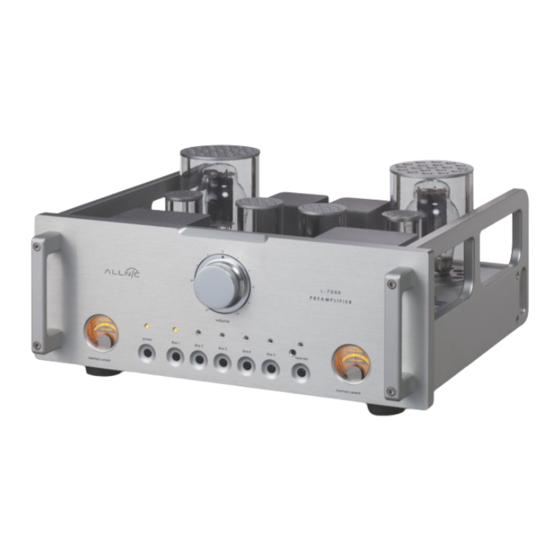
Page 4: Introducing The L-7000 Line-Stage Preamplifier
INTRODUCING THE L-7000 LINE-STAGE PREAMPLIFIER Immerse yourself in the original recorded space. The L-7000 is a single gain stage, transformer- coupled, remote controlled line-stage pre-amplifier. It uses the 300B direct-heated triode as a voltage regulator. The 300B has justly won the reputation for being a superb output tube in single-ended amplifier, but it will take some rethinking to imagine this great tube in a role outside the signal path. - Page 5 Precision attenuator volume control – The L-7000 does not employ a digital IC volume control or a low-cost carbon film volume control with a motor. The L-7000 uses the WORLD’S FIRST 61 step, constant impedance, “bridged” type attenuator, standard on all units produced after May 2019.
-
Page 6: What's In The Box
NOT connect it to your AC outlet. Please contact your Allnic dealer. We advise that you keep the box and other packing materials that your L-7000 came in. It will be useful if you sell your L-7000 or in the unlikely event you need to ship it for service. -
Page 7: Safety
INITIAL SET-UP LOCATION, LOCATION, LOCATION Like all audio products using tubes, the Allnic Audio L-7000 needs to be placed on a solid stand in a location that provides for good air circulation around the preamplifier. •... -
Page 8: Power Connection
The L-7000 will be set internally for your location’s electrical system characteristics. Please check the setting for electrical input on the label on the rear of the unit to confirm that your L-7000 matches your location’s electrical system. For North American customers, the L-7000 is set internally for AC 110/120 volt –... -
Page 9: Phase Switch
Push the power on-off switch to the left of the IEC connector (facing the left side of the unit as in Figure 1) so it is in the “on position”. That will power up the L-7000. From this point on, you need only use the far left hand button marked “power”... -
Page 10: Operation
The needle should be between the two parallel lines just left of centre on the meter face. Any failure of the tubes or circuits in one or the other of the L-7000 ’s channels is indicated by the needle on the meter for the respective channel moving out from between those two parallel lines. -
Page 11: Specifications
Audio and its authorized representatives are not liable in any way whatsoever for any injury or loss incurred by the user or for damage to the L-7000, any of its parts, or tubes or replacement tubes resulting from the user changing or attempting to change tubes. -
Page 12: Warranty
Audio’s authorized representative for warranty service prior to any unauthorized attempt to repair or modify it. Any repair done to or modification of this Allnic Audio product at any time performed without specific authorization from Allnic Audio or its authorized representative will void the warranty. -
Page 13: Figures
FIGURES Figure 1 – L-7000 Left Side Panel View Figure 2 – L-7000 Rear Panel View... - Page 14 Figure 3 – L-7000 Remote Control Figure 4 – L-7000 Front Panel View...
- Page 15 Figure 5 – L-7000 Top View...
Need help?
Do you have a question about the L-7000 and is the answer not in the manual?
Questions and answers