Table of Contents
Advertisement
Quick Links
Advertisement
Table of Contents

Related Manuals for ALLNIC AUDIO L-9000


Summary of Contents for ALLNIC AUDIO L-9000
- Page 1 ALLNIC AUDIO L-9000 OTL/OCL LINE-STAGE PREAMPLIFIER OWNER’S MANUAL...
- Page 2 Audio and its dealers worldwide, as well as your appreciation for the sound of this high- quality device, will be rewarded by its excellent operation for years to come. Please read this entire manual before you connect the L-9000 OTL/OCL Line-Stage Preamplifier to the other components of your system and the wall outlet.
-
Page 3: Table Of Contents
CURRENT METERS TUBES SPECIFICATIONS WARRANTY FIGURES Please read about SAFETY before you attempt to use the L-9000 OTL/OCL Line-Stage Preamplifier - we care about our customers and the equipment, and we want you to enjoy this product for a long time! -
Page 4: Introducing The L-9000 Otl/Ocl Line-Stage Preamplifier
Instrument and vocal tones and timbres are breathtakingly lifelike, and the placement of instruments and bodies in three dimensions startling, life-size, and addictive. The L-9000 OTL/OCL has no voice of its own, none. It is silent, except for the music... - Page 5 61 STEP CONSTANT IMPEDANCE BRIDGED TYPE ATTENUATOR - A world’s “first of its kind” for Allnic Audio The L-9000 OTL/OCL does not employ a digital IC volume control or a low-cost carbon film volume control with a motor. The L-9000 OTL/OCL uses the WORLD’S FIRST 61 step, constant impedance, “bridged”...
-
Page 6: What's In The Box
L-9000 OTL/OCL in your system. 3) Be sure the L-9000 OTL/OCL is labeled for the AC voltage of your location. If it is not, DO NOT connect it to your AC outlet. Please contact your Allnic dealer. -
Page 7: Cleaning
INITIAL SET-UP A. LOCATION, LOCATION, LOCATION Like all audio products using tubes, the Allnic Audio L-9000 OTL/OCL needs to be placed on a solid stand in a location that provides for good air circulation around the preamplifier. •... -
Page 8: Inputs
- while you make all initial connections. The L-9000 OTL/OCL you have purchased is set internally for AC 110/120 volt – 60 HZ, or 220/230 volt – 50 Hz operation. There is no way to change this to another AC setting without return of the unit to the factory for re-wiring, at the owner’s cost, including transport both directions. -
Page 9: Initial Power On
Push the power on-off switch to the left of the IEC connector (facing the left side of the unit as in Figure 1) so it is in the “on position”. That will power up the L-9000 OTL/OCL. From this point on, you need only use the far left hand button marked “power”... -
Page 10: Operation
Please be patient; it could take some time to get an approximate balance, but once set, it should rarely, if ever, move. The Allnic Audio L-9000 OTL/OCL is now ready for operation. At this point, you can power on your sources and, finally, your stereo power amplifier or mono-blocks. -
Page 11: Current Meters
L-9000 OTL/OCL, any of its parts, or tubes or replacement tubes resulting from the user changing or attempting to change tubes. -
Page 12: Specifications
SPECIFICATIONS FOR THE ALLNIC AUDIO L-9000 OTL/OCL LINE-STAGE PREAMPLIFIER • Inputs: Line level × 5 pairs: Balanced (XLR) × 2 Unbalanced (RCA) × 3 • Outputs: 3 pairs: Unbalanced (RCA) × 2 pairs Balanced (XLR) × 1 pair • Input 10kΩ... -
Page 13: Warranty
Date of purchase is the date indicated on the invoice for the product issued by Allnic Audio or its authorized representative. For the warranty to be valid, a defective product must be returned to Allnic Audio’s authorized representative for service prior to any unauthorized attempt to repair. -
Page 14: Figures
FIGURES Figure 1 – L-9000 OTL/OCL Left Side Panel View... - Page 15 Figure 2 – L-9000 OTL/OCL Rear Panel View Figure 3 – L-9000 OTL/OCL Remote Control...
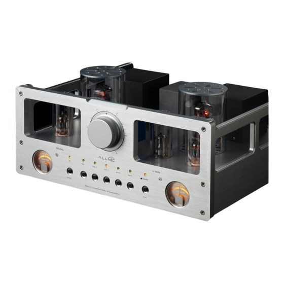
- Page 16 Figure 4 – L-9000 OTL/OCL Front Panel View...
- Page 17 Figure 5 – L-9000 OTL/OCL Top View...
Need help?
Do you have a question about the L-9000 and is the answer not in the manual?
Questions and answers