
Related Manuals for Star Headlight & Lantern Signal LCS850MG


Summary of Contents for Star Headlight & Lantern Signal LCS850MG
- Page 1 INSTALLATION AND INSTRUCTION MANUAL LCS850MG LCS850MG LCS850MG LCS850MG SIREN AMPLIFIER & LIGHT CONTROLLER A Division of Star Headlight & Lantern Co., Inc. PLIT426 REV. C 12/13/10...
- Page 2 Installation Information INSTALLATION INFORMATION LCS850MG MODEL: AMPLIFIER SERIAL #: CONTROL HEAD SERIAL #: PURCHASE DATE: DEALER: INSTALLER: INSTALLATION DATE: CONTROL HEAD DIP SWITCH OPTIONS _____ Keypad Beep _____ Gun Lock _____ TD Mode _____ AUX Wire _____ Audio Pursuit _____ Visual Pursuit _____ Progressive Slide Switch _____ TD Output _____ Auto On...
-
Page 3: Table Of Contents
Table of Contents TABLE OF CONTENTS OVERVIEW PRECAUTIONS CONTENTS SPECIFICATIONS INSTALLATION 4-44 INSTALLER-SELECTABLE OPTIONS 4-34 Control Head DIP Switch Settings Overview Chart BUZZ (Beep Settings), Gun Lock, Traffic Director Mode AUX (Auxiliary Input), Audio Pursuit, Progressive Slide Switch TD Output, Auto On, Magnum Mode Radio, Phaser, Sweep, Programming Mode Amplifier Dip Switch Settings Traffic Director Settings... -
Page 4: Overview
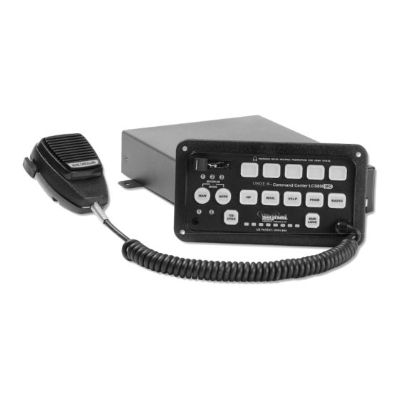
Overview LCS850MG Overview The LCS850MG Siren Amplifier is a premium 200W unit designed for dual 100W speaker use and full lighting control. It comes standard with a remote control head and a noise-cancelling microphone for PA use. The amplifier box contains two separate amplifiers that allow the user to operate two separate and distinct tones at the same time. -
Page 5: Precautions
Installation Information NOTICE Due to continuous product improvements, we must reserve the right to change any specifications and information, contained in this manual at any time without notice. Signal Vehicle Products and/or the manufacturer make no warranty of any kind with regard to this manual, including, but not limited to, the implied warranties of merchantability and fitness for a particular purpose. -
Page 6: Specifications
Specifications Specifications Input Voltage 10 - 16 VDC (negative ground) Input Current 8.0 Amps @ 13.6 VDC (single 100W speaker) 16.0 Amps @ 13.6 VDC (dual 100W speakers) Standby Current 0 mA while Off, <150 mA with backlighting on Max Peak Current 50 AMPS (supply circuit must be capable of supplying this for brief period) Audio Frequency 200Hz - 10 kHz + 3db... -
Page 7: Installation
Installation Control Head Dip Switch Settings Overview Installation Signal Vehicle recommends that you bench test the unit immediately after receipt to ensure that it was not damaged in shipping. Then you should program all settings and test again prior to installation. -
Page 8: Control Head Dip Switch Settings
Installation: Dip Switch Settings Control Head Dip Switch Settings (cont’d) Buzz, Gun Lock, TD Mode LCS850MG-CH DIP Switches—Detailed Information 11 12 13 14 There are two sets of DIP switches located on the back of the Control Head. One set has ten switches and the other has four. -
Page 9: Aux (Auxiliary Input), Audio Pursuit, Progressive Slide Switch
Installation: Dip Switch Settings Control Head Dip Switch Settings (cont’d) AUX Wire, Audio Pursuit, Visual Pursuit, and Progressive SS AUX (Auxiliary Wire Input Function) The auxiliary input (terminal 7 of the 10-terminal connector, see page 41) Activates allows you to either activate the Air Horn, or to "mimic" the Manual button Manual Function function, through some other external switch, such as the vehicle horn Activates... -
Page 10: Td Output, Auto On, Magnum Mode
Installation: Dip Switch Settings Control Head Dip Switch Settings (cont’d) TD Output, Auto On, Magnum Mode 11 12 13 14 DISCRETE TD (Traffic Director Compatibility: 8-Output or 4-Output Logic) If you will be connecting a Traffic Director to this unit, be sure that you have set the Discrete TD DIP switch (switch #3) for Traffic Director Mode ON (switch in down position as explained on page 5). -
Page 11: Radio, Phaser, Sweep, Programming Mode
Installation: Dip Switch Settings Control Head Dip Switch Settings (cont’d) Radio, Phaser, Sweep, Programming Mode RADIO DISABLE (Radio Rebroadcast or ON/OFF Switch for Output 7) By default, the RADIO button is used to rebroadcast the two-way radio over the PA system of the siren. If you will not be using this feature, you can instead use the RADIO button to control another device, attached to Output 7. -
Page 12: Amplifier Dip Switch Settings
Installation Amplifier DIP Switch Settings AUX Input Polarity and Park-Kill Polarity Amplifier DIP Switch Settings There are four additional DIP switches located on the amp box near the connectors (see diagram below). These four switches are used to control the polarity of your Auxiliary function and your Park-Kill function. -
Page 13: Traffic Director Settings
Installation Traffic Director Settings Traffic Director Settings This section only applies to those applications in which the TD CYCLE on the control head will be used to operate a traffic director (arrowstick). If you are NOT using this button to control a traffic director, you can skip to page 14, after ensuring that DIP switch 3 (TD MODE), on the back of the Control Head, is in the OFF position (see page 5). - Page 14 Installation Traffic Director Settings: Standard 8-Head Traffic Directors (cont’d) Internal TD DIP Switches There are several additional programmable options for standard 8-head (or 6-head) traffic directors that utilize the internal controller. Review these option below and determine if you will need to change any of the default settings.
- Page 15 Installation Traffic Director Settings: Standard 8-Head Traffic Directors (cont’d) Low Power (switch 2/bank 1) If the arrow stick is to be used for nighttime operation, or you wish to reduce the power consumption of the arrow stick, the output can be reduced by 50%. To set your arrowstick to run under Low Power, move this DIP switch TOWARDS the edge of the siren.
-
Page 16: Traffic Directors With Internal Controllers
Installation Traffic Director Settings: Traffic Directors with Built-In Controllers Traffic Directors with Built In Controllers This section only applies to those Traffic Directors that have a built-in controller, but will be operated with the TD CYCLE button through “signal” wires. The LCS850MG has three different compatibility modes that can be used, depending upon the input requirements of your Traffic Director. -
Page 17: Programmable Settings
Installation: Detailed Programming Detailed Programming Summary Table Detailed Programming Summary Table The options below should be programmed PRIOR to installation of your siren. Refer to pages 15-34 for detailed programming instructions. Option Default Setting Optional Setting Button Operation Activating a Button (Turning it on) Will Activating Button (Turning it on) Opens (Open or Closed) Apply +12VDC (Closed) -
Page 18: Detailed Programming Legend
Installation: Detailed Programming Detailed Programming Legend AUDIO PUSH DEFAULT MODE FUNCTION DEFINITION BUTTON SETTING BUTTON Gun Lock Buttons ALL PB ONLY PB4 PB3 PB4 PB13 PB14 Button Operation (Open or Closed) WAIL ALL PB ALL OPEN PB3 PB4 PB13 PB14 YELP ALL PB ALL STEADY Steady or Flashing/Pulsed Outputs... -
Page 19: Detailed Programming Instructions (See Page 14 For Specific Page Numbers For Each Option)
Installation: Detailed Programming Placing the Siren Into Programming Mode Detailed Programming Instructions The following section gives a detailed description of how to program each of the options listed on the previous two pages. If you do not need to change any of these options, you may skip to the Mounting section on page 35. - Page 20 Installation: Detailed Programming Button Operation (Open or Closed) Button State at Power Up All options on pages 17 All options on pages 17 All options on pages 17 All options on pages 17- - - - 34 can be programmed via USB cable using the enclosed CD 34 can be programmed via USB cable using the enclosed CD 34 can be programmed via USB cable using the enclosed CD 34 can be programmed via USB cable using the enclosed CD...
- Page 21 Installation: Detailed Programming Button Operation (Latched or Momentary) Auto Beep Option All options on pages 17 All options on pages 17 All options on pages 17 All options on pages 17- - - - 34 can be programmed via USB cable using the enclosed CD 34 can be programmed via USB cable using the enclosed CD 34 can be programmed via USB cable using the enclosed CD 34 can be programmed via USB cable using the enclosed CD...
- Page 22 Installation: Detailed Programming Gun Lock Button Assignment Gun Lock Timer Period All options on pages 17 All options on pages 17 All options on pages 17 All options on pages 17- - - - 34 can be programmed via USB cable using the enclosed CD 34 can be programmed via USB cable using the enclosed CD 34 can be programmed via USB cable using the enclosed CD 34 can be programmed via USB cable using the enclosed CD...
- Page 23 Installation: Detailed Programming Gun Lock Pass Code Enable All options on pages 17 All options on pages 17 All options on pages 17 All options on pages 17- - - - 34 can be programmed via USB cable using the enclosed CD 34 can be programmed via USB cable using the enclosed CD 34 can be programmed via USB cable using the enclosed CD 34 can be programmed via USB cable using the enclosed CD...
- Page 24 Installation: Detailed Programming Setting Gun Lock Pass Code Radio/PA Diagnostic POP All options on pages 17 All options on pages 17 All options on pages 17 All options on pages 17- - - - 34 can be programmed via USB cable using the enclosed CD 34 can be programmed via USB cable using the enclosed CD 34 can be programmed via USB cable using the enclosed CD 34 can be programmed via USB cable using the enclosed CD...
- Page 25 Installation: Detailed Programming Steady or Pulsed Output Options All options on pages 17 All options on pages 17 All options on pages 17 All options on pages 17- - - - 34 can be programmed via USB cable using the enclosed CD 34 can be programmed via USB cable using the enclosed CD 34 can be programmed via USB cable using the enclosed CD 34 can be programmed via USB cable using the enclosed CD...
- Page 26 Installation: Detailed Programming Manual Step Up Function Time Out Manual Wind Down in Standby or HF All options on pages 17 All options on pages 17 All options on pages 17 All options on pages 17- - - - 34 can be programmed via USB cable using the enclosed CD 34 can be programmed via USB cable using the enclosed CD 34 can be programmed via USB cable using the enclosed CD 34 can be programmed via USB cable using the enclosed CD...
- Page 27 Installation: Detailed Programming Siren Disable Audio Lockout All options on pages 17 All options on pages 17 All options on pages 17 All options on pages 17- - - - 34 can be programmed via USB cable using the enclosed CD 34 can be programmed via USB cable using the enclosed CD 34 can be programmed via USB cable using the enclosed CD 34 can be programmed via USB cable using the enclosed CD...
- Page 28 Installation: Detailed Programming Audio Pursuit Options All options on pages 17 All options on pages 17 All options on pages 17 All options on pages 17- - - - 34 can be programmed via USB cable using the enclosed CD 34 can be programmed via USB cable using the enclosed CD 34 can be programmed via USB cable using the enclosed CD 34 can be programmed via USB cable using the enclosed CD...
- Page 29 Installation: Detailed Programming Audio Pursuit Mode, HF Mode at Boot Quick Shot Tone Replaces Air Horn All options on pages 17 All options on pages 17 All options on pages 17 All options on pages 17- - - - 34 can be programmed via USB cable using the enclosed CD 34 can be programmed via USB cable using the enclosed CD 34 can be programmed via USB cable using the enclosed CD 34 can be programmed via USB cable using the enclosed CD...
- Page 30 Installation: Detailed Programming Second Tone Swap All options on pages 17 All options on pages 17 All options on pages 17 All options on pages 17- - - - 34 can be programmed via USB cable using the enclosed CD 34 can be programmed via USB cable using the enclosed CD 34 can be programmed via USB cable using the enclosed CD 34 can be programmed via USB cable using the enclosed CD...
- Page 31 Installation: Detailed Programming 3 3 3 3 Tone Sweep Disable in HF for Slide Switch High-Low (Two-Tone) Override of Phaser Tone All options on pages 17 All options on pages 17 All options on pages 17 All options on pages 17- - - - 34 can be programmed via USB cable using the enclosed CD 34 can be programmed via USB cable using the enclosed CD 34 can be programmed via USB cable using the enclosed CD 34 can be programmed via USB cable using the enclosed CD...
- Page 32 Installation: Optional Settings Horn Ring Transfer (HRT) Options All options on pages 17 All options on pages 17 All options on pages 17 All options on pages 17- - - - 34 can be programmed via USB cable using the enclosed CD 34 can be programmed via USB cable using the enclosed CD 34 can be programmed via USB cable using the enclosed CD 34 can be programmed via USB cable using the enclosed CD...
- Page 33 Installation: Detailed Programming Slide Switch Programming All options on pages 17 All options on pages 17 All options on pages 17 All options on pages 17- - - - 34 can be programmed via USB cable using the enclosed CD 34 can be programmed via USB cable using the enclosed CD 34 can be programmed via USB cable using the enclosed CD 34 can be programmed via USB cable using the enclosed CD...
- Page 34 Installation: Detailed Programming Slide Switch Options Auto-Off Traffic Director Visual Pursuit All options on pages 17 All options on pages 17 All options on pages 17 All options on pages 17- - - - 34 can be programmed via USB cable using the enclosed CD 34 can be programmed via USB cable using the enclosed CD 34 can be programmed via USB cable using the enclosed CD 34 can be programmed via USB cable using the enclosed CD...
- Page 35 Installation: Detailed Programming Logic Controlled TD Programming: Output Select and Polarity All options on pages 17 All options on pages 17 All options on pages 17 All options on pages 17- - - - 34 can be programmed via USB cable using the enclosed CD 34 can be programmed via USB cable using the enclosed CD 34 can be programmed via USB cable using the enclosed CD 34 can be programmed via USB cable using the enclosed CD...
- Page 36 Installation: Optional Settings Optional Input Functions: Gun Lock Button Enable and Dim All options on pages 17 All options on pages 17 All options on pages 17 All options on pages 17- - - - 34 can be programmed via USB cable using the enclosed CD 34 can be programmed via USB cable using the enclosed CD 34 can be programmed via USB cable using the enclosed CD 34 can be programmed via USB cable using the enclosed CD...
-
Page 37: Resetting Unit To Defaults
Installation: Detailed Programming Park-Kill De-activation of Lights Reset To Factory Defaults All options on pages 17 All options on pages 17 All options on pages 17 All options on pages 17- - - - 34 can be programmed via USB cable using the enclosed CD 34 can be programmed via USB cable using the enclosed CD 34 can be programmed via USB cable using the enclosed CD 34 can be programmed via USB cable using the enclosed CD... -
Page 38: Mounting
Installation: Mounting Mounting Mounting Safety Precautions For the safety of the installer, vehicle operator, passengers, and the community please observe the following safety precautions. Failure to follow all safety precautions and instructions may result in property damage, injury or death. !!! WARNING !!! DO NOT mount in airbag deployment area!!!. - Page 39 Installation: Mounting Control Head Control Head The standard control head can be mounted using either an adjustable “U” bracket, or mounted directly to a plate or other flat surface using the flange. • Verify that you have already set all of the applicable option jumpers on the control head. •...
- Page 40 Installation: Mounting Siren Amplifier and Relay Control Box Microphone Bracket Siren Amplifier and Relay Control Box The LCS850MG amplifier should be mounted in a location such as the driver compartment firewall, under the seat, or in the trunk. Do not mount the amplifier in the engine compartment, or in an area that would be allowed direct exposure to weather elements.
-
Page 41: Electrical Connections
Installation Electrical Connections Electrical Connections The following steps are recommended when installing, to help reduce RFI: • Make sure that both the control head and amp are securely attached to good chassis ground (i.e. no paint in-between the chassis and the grounding terminal). •... -
Page 42: Power And Ground Connections
Installation Electrical Connections (CONT’D Power and Ground Wiring Connections Slide Switch and Push Communications Port Audio I/O Button Outputs CPU Serial Interface Battery Traffic Director Outputs Power Negative Electrical connections to the unit are made using several terminals and removable connectors located on both the front and back of the unit. -
Page 43: 10-Terminal Connector (Ss And Pushbutton Outputs)
Installation: Wiring Slide Switch and Push Button Outputs Slide Switch and Push Button Outputs P30041-177 The slide switch and push button switch outputs are all made on a 10-terminal connector (P/N P30041-177). Be sure to use a wire size that is appropriate for the load each will be carrying (see pages 39-43). - Page 44 Installation Wiring Diagram #1 10-Terminal Connector Siren Wiring Diagram #1 Inputs and Light Outputs Please note that the screws should be located on the top of this connector, as it plugs into the back of the unit. P30041-177 BATTERY PB1-PB5, PB13, PB14 Lights Slide Switch Lights See the charts on pages 39-40 for proper wire sizes!!
-
Page 45: Label Insertion
Installation: Wiring 12-Terminal Connector (Audio I/O) (CONT’D) Label Insertion Label Insertion Once the wire connections have been made to PB1-PB5, PB13, and PB14 , labels can be inserted into the switches. The product is shipped with 49 different labels for these push buttons. -
Page 46: 12-Terminal Connector (Audio I/O)
Installation: Wiring 12-Terminal Connector (Audio I/O) 12-Terminal Audio Connector Inputs and Outputs (See wiring diagram on page 44) P30041-68 Terminal 1: Speaker 2 (Negative) - <BROWN> Connect to the negative terminal from your second speaker. Use a minimum 14 AWG wire. Terminal 2: Speaker 2 (Positive) - <BROWN w/WHITE>... - Page 47 Installation Wiring Diagram #2 12-Terminal Connector SPEAKER 2 11 OHMS SPEAKER 1 11 OHMS -44-...
-
Page 48: Slide Switch
Operation Slide Switch and Pushbuttons Operation General This unit is designed for easy operation under the stress associated with high-speed pursuit. Most siren functions and/or light controls are accessible with one simple motion without repetitive activation of switches or automatic timed switching that can interfere with desired operation. Slide Switch The slide switch is designed for quick pursuit mode operation. -
Page 49: Audio Mode Buttons
Operation Audio Mode Buttons Volume Controls Audio Mode Buttons There are five (5) push buttons across the middle of the control head that are used to select which “audio mode” you would like the siren to be in. When these buttons are NOT activated, they are backlit in green for nighttime viewing. -
Page 50: Manual Buttons
Operation MAN Button Additional Audio Control Buttons There are two (2) other push buttons across the middle of the control head that are used to control additional audio functions, the MAN and HORN buttons. Manual (MAN): In Standby (no Audio Modes activated) or Hands Free Mode, this momentary push button switch provides a manually activated “Momentary Wind Up”... -
Page 51: Air Horn
Operation Air Horn Magnum Mode Air Horn (HORN): This momentary push button switch provides a simulated air-horn tone while pressed. This can be used to either replace, or to supplement the normal vehicle horn and is useful at intersections or in high noise areas. This tone will override all other siren tones. -
Page 52: Traffic Director Control Buttons
Operation Traffic Director Control Button, Speaker Diagnostics, Microphone, Auxiliary Input, and Park-Kill Traffic Director Control Button (PB13) By default, button PB13 is designed for use with a compatible arrowstick (traffic director) and P14 is set to be used for a Gun Lock release. Both buttons can be used to control other functions if you will not be connecting a traffic director or Gun Lock. -
Page 53: Cloning
Cloning Cloning The LCS850MG has been designed to allow for the settings of one unit to be “cloned” or copied to another unit, thus reducing the time that it takes to program multiple units. This feature is extremely useful when setting up fleets of vehicles that will all be using the same (or similar) options. -
Page 54: Service
Service Fuses and Parts Service Fuses The outputs on this unit are protected by ten 20 Amp automotive type blade fuses. They are located inside the amp and are accessible through the removable access panel. 1. To access the fuses, loosen the two Phillips head screws that secure the access cover to the top of the siren, and remove the cover. -
Page 55: Troubleshooting
Service Troubleshooting This unit is designed to provide years of reliable service under even the worst conditions. Many times there may appear to be a problem with the unit when the true problem is in the speaker(s) or improper installation. The following chart shows typical symptoms and possible causes. Troubleshooting Symptom Possible Cause... -
Page 56: Warranty
Warranty and Return LIMITED WARRANTY Signal Vehicle Products warrants this new product to be free from defects in material and workmanship, under normal use and service, for a period of one (1) year from the date of delivery to the first user-purchaser. During this warranty period the obligation of Signal Vehicle Products is limited to repair- ing or replacing, as Signal Vehicle Products may elect, any part or parts of such product which after examination by Signal Vehicle Products is determined to be defective in material... -
Page 57: Returned Goods Authorization Form
Returned Materials Authorization Form If a problem with this product develops within the warranty period, please contact our Customer Service Department at (585) 226-9025. When contacting us about a product you have purchased, please have the product’s serial number readily available. If the product needs to be returned, you will be issued an RMA number (Returned Materials Authorization Number).
Need help?
Do you have a question about the Signal LCS850MG and is the answer not in the manual?
Questions and answers