Advertisement
Quick Links
E lec t r if i e d L o c k s, Re l ay s a n d Tim ers
WC16PS Series Restroom Control
INSTALLATION INSTRUCTIONS
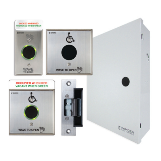
1. GENERAL DESCRIPTION
The Restroom Control Kit allows access in and out of a Restroom,
with the ability to secure the door and make patrons aware that
the location is either occupied or vacant while using Camden's
hands-free SURE-WAVE touchless switches.
The CX-WC16PS Series of Restroom Control Kits are controlled by
Camden's advanced relay logic controller part number CX-33. The
CX-33 currently has 2 pre-set modes that will accommodate most
Restroom applications, Mode 7 (normally unlocked) or Mode
8 (normally locked). The default Mode for the CX-WC16PS
is Mode 7 (normally unlocked). Each Restroom Control Kit
will have the ability to physically open the door then allow the
patron to lock the door once inside. When locked, the CX-33 will
change the coloring of the inside & outside SURE-WAVE touchless
switches (with the SGLR light ring option) from green to red,
displaying that the Restroom is in use. When the inside WAVE TO
OPEN switch is activated it will unlock the door, then physically
open the door and change the color of the inside & outside
WAVE TO OPEN touchless switches SGLR light ring back to green,
displaying that the Restroom is now vacant. The locked Restroom
can be unlocked by either activating the inside WAVE TO OPEN
touchless switch, or by using the crash bar, paddle or turning the
knob set to open the door. Either method will reset the SGLR light
ring back to green.
The CX-WC16PS Series of Restroom Control Kits kit uses
Camden's CM-331/42WS-SGLR as the outside WAVE TO OPEN,
the CM-325/42WS as the inside WAVE TO OPEN and the
CM-331/43S-SGLR as the WAVE TO LOCK. The SGLR circuit board
is installed on the front of the outside WAVE TO OPEN and on
the front of the inside WAVE TO LOCK touchless switches making
them easily seen by patrons at a distance.
2. INSTALLATION
Operation at a Glance
When the outside WAVE TO OPEN touchless switch is activated
it will trigger its N.O. relay contact to send a momentary closure
to the CX-WC16PS allowing the door to swing open.
When the interior WAVE TO LOCK touchless switch is activated it
will trigger its N.O. relay contact to send a momentary closure to
the CX-WC16PS to lock the Restroom and switch the SGLR light
Page 1 of 13
ring color from green to red. The inside WAVE TO OPEN. When
activated will unlock the door, and the door will swing open.
The Restroom can also be unlocked by opening the door from
the inside which will break the door contact circuit causing the
CX-WC16PS to reset and unlock the door. The SGLR light ring
will switch back to green signalling the Restroom is
now vacant.
Mounting
IMPORTANT: Do not apply power to the unit until you
have fully read the instructions and have made the
required adjustments.
The CX-WC16PS cabinet should be mounted in a clean dry
location out of direct contact with the elements.
Wiring the CX-WC16PS Series Restroom
Control Kit is as follows:
The CX-WC16PS comes with the CX-33 pre-wired to a labeled set
of two terminal strips. This will make the wiring of the WAVE TO
OPEN/WAVE TO LOCK sensors easier since the wiring manual
will no longer need to be directly referenced for termination
points. A complete wiring diagram is adhered to the inside of
the door to provide a layout of the wiring as a reference when
wiring the field devices to the kit.
There are two terminal strips that mirror the locations on the
CX-33. The left strip is used for power to the CX-33, the PUSH
TO OPEN (WAVE TO OPEN) and PUSH TO LOCK (WAVE TO LOCK)
sensors, the door position switch, and the Wet trigger. The
right strip is for the outputs to drive the strike (Relay 1), door
operator (Relay 2), SGLR light ring (Relay3), and to provide VDC
power for the door strike.
All SURE-WAVE devices can be powered with 12/24 VAC/VDC.
Note: The SGLR option (light ring) must be installed before
applying power to the sensor.
Advertisement

Related Manuals for CAMDEN CX-WC16PS Series


Summary of Contents for CAMDEN CX-WC16PS Series
- Page 1 Restroom is hands-free SURE-WAVE touchless switches. now vacant. The CX-WC16PS Series of Restroom Control Kits are controlled by Mounting Camden’s advanced relay logic controller part number CX-33. The IMPORTANT: Do not apply power to the unit until you...
- Page 2 Editing the Settings for a Mode Wiring the Inside WAVE TO OPEN Sensor Camden builds in typical times for lock release and door (CM-325/42WS) operator activation and is ready to use without changing any parameters. If you need to change the timing or delay for an Wire in power using the two red wires (not polarity sensitive).
- Page 3 WC16PS SERIES RESTROOM CONTROL I NSTA LLAT I O N I N S T RU C T I O N S Display (M) Description ( Mode you are in) Parameters ( 1-15 ) H, then 1 Relay 1 Hold Time 0.0 to 50 seconds d, then 1 Relay 2 Delay Time...
- Page 4 WC16PS SERIES RESTROOM CONTROL IN S TALL AT ION INSTRUCTIO NS SINGLE GANG ELECTRICAL BOX MOUNT - CM-331/43S-SGLR 1. a) If using an in-wall box ensure the box is plumb and 5. Attach the unit to the enclosure using the two #6-32 square, and flush with the wall surface.
- Page 5 WC16PS SERIES RESTROOM CONTROL I NSTA LLAT I O N I N S T RU C T I O N S DOUBLE GANG ELECTRICAL BOX MOUNT - CM-331/42SW-SGLR - CM-325/42SW 1. a) If using an in-wall box ensure the box is plumb and 4.
-
Page 6: In-Wall Mounting
WC16PS SERIES RESTROOM CONTROL IN S TALL AT ION INSTRUCTIO NS IN-WALL MOUNTING Proper Mounting Improper Mounting Smooth Wall Finish Rough Finished Wall Wall Recessed Box Unaligned Box Flush Sure-Wave™ In-Wall Box SUREWAVE ASSEMBLY Surface Mount Enclosure A.OLISA MAR-20 CM-331/42SW-SGLR CM-325/42SW Sealing Gasket #6-32 x 3/4”... -
Page 7: Installation
WC16PS SERIES RESTROOM CONTROL CX-ED2079 ‘Universal’ Electric Strike I NSTA LLAT I O N I N S T RU C T I O N S 4. Installation CX-ED2079 'UNIVERSAL' ELECTRIC STRIKE INSTALLATION 1. Prepare the door jamb as per the appropriate drawing. bracket &... -
Page 8: Operation
CX-ED2079 ‘Universal’ Electric Strike WC16PS SERIES RESTROOM CONTROL 5. Connections 6. Operation IN S TALL AT ION INSTRUCTIO NS CONNECTIONS OPERATIONS POWER How to modify fail-safe to fail-secure or vice versa. 12VDC 24VDC 1. Loosen the screw as per the product diagram below. Red/Black: +12V Red:... -
Page 9: Ordering Information For Replacement Parts
WC16PS SERIES RESTROOM CONTROL I NSTA LLAT I O N I N S T RU C T I O N S ORDERING INFORMATION FOR REPLACEMENT PARTS Item Part Number Description 60-31A008 Line Powered Surewave, 1 Relay for CM-331/43S-SGLR & CM-331/42SW-SGLR 60-31A006 Touchless IR Sensor Short Range for CM-325/42SW 60-40E035... - Page 10 WC16PS SERIES RESTROOM CONTROL IN S TALL AT ION INSTRUCTIO NS Notes : Questions? Call us toll-free at 1-877-226-3369 or technical support 905-366-3377 (ext. 505) File: WC16PS Restroom Controls Opening New Doors to Call: 1.877.226.3369 / 905.366.3377 Manual.indd Innovation, Quality and Support! Visit: www.camdencontrols.com Rev.: September 13, 2023 Part No: 40-82B239...
- Page 12 Mode 8 (Normally Locked). Notes 2. Mode 7 = Set Set Strike to Fail Safe. 3. Mode 8 = Set Strike to Fail Secure. 5502 Timberlea Blvd CAMDEN DOOR CONTROLS Mississauga, Ontario L4W 2T7 Enable (DIP 1) Mode (DIP 2)
Need help?
Do you have a question about the CX-WC16PS Series and is the answer not in the manual?
Questions and answers