
Subscribe to Our Youtube Channel
Related Manuals for CENTR 2


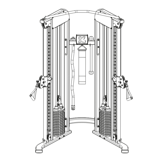
Summary of Contents for CENTR 2
- Page 1 Model: FTX.3 USER MANUAL CENTR 2 FUNCTIONAL TRAINER Record Serial Number Here MADE IN CHINA V06232023...
- Page 2 V06232023...
-
Page 3: Product Warranty
WELCOME Welcome to Centr and thanks for your purchase. We're happy to have you. Please inspect your product and contact us right away if anything is missing or damaged. Your equipment also comes with access to Centr's digital membership, unlocking tools that will fuel your active lifestyle and well-being. - Page 4 V06232023...
-
Page 5: Table Of Contents
TABLE OF CONTENTS PRODUCT WARRANTY..................4 IMPORTANT SAFETY NOTICE.................6 FUNCTIONAL TRAINER ASSEMBLY INSTRUCTIONS.......8 DECAL PLACEMENT..................12 LIVE AREA......................13 PRODUCT DIMENSIONS.................14 MAINTENANCE....................15 MAINTENANCE SCHEDULE................15 EXPLODED DIAGRAM..................16 PARTS LIST......................17 V06232023 Pg. 5... -
Page 6: Important Safety Notice
12. Never operate the machine if the machine is not functioning properly. 13. The Centr 2 Functional Trainer is designed for home use only. Therefore, it does not have a weight stack cover. This means the following for the user: •... - Page 7 Part #23 (Ø10; 4 pcs) Part #23 (Ø10; 4 pcs) Part #25 (Ø10; 20 pcs) Part #25 (Ø10; 20 pcs) Part #29 (Ø6; 2 pcs) Part #29 (Ø6; 2 pcs) Part #19 (M10*70; 8 pcs) Part #19 (M10*70; 8 pcs) Part #24 (M10;...
-
Page 8: Functional Trainer Assembly Instructions
A. Do not tighten the Nuts and Bolts until instructed to do so. B. Place the Lower Cross Brace (#4) between the Right & Left Stations (#1 & #2) in the mid-span. C. Attach one end of the Lower Cross Brace to the Right Station. Secure it with two M10 x 70 Allen Bolts (#19) four Ø... - Page 9 Assembly (#8) starts lifting slightly from the weight stack. Tighten the nut of the cam bolt to lock it’s position. M. Repeat the Procedure A through L above to install the other set of weight plates to the Left Station. (#2) V06232023 Pg.
- Page 10 Pg. 10 V06232023...
- Page 11 STEP 3 A. Attach the Height Adjustment Handle (#15) to the Left Lock Switch (#35) on the Pulley Carriage, secure it with one M5 x 10 Allen Bolt (#22). Repeat the same procedure to install the other side. B. Connect the Single Handle (#13) to the Cable (#1) on the Right Station (#1) with a Spring Clip (#17). Repeat the same procedure to install the other side.
-
Page 12: Decal Placement
DECAL PLACEMENT Pg. 12 V06232023... -
Page 13: Live Area
LIVE AREA 2.7 m 9 ft 9 pi 2.4 m 8 ft 8 pi 2.4 m 8 ft 8 pi V06232023 Pg. 13... -
Page 14: Product Dimensions
PRODUCT DIMENSIONS 210 cm 82.6 inch 82.6 po 140 cm 55.1 in 55.1 po 137 cm 53.9 in 53.9 po Pg. 14 V06232023... -
Page 15: Maintenance
Inspect: Anti-Skid surfaces Clean and Lubricate: Guide Rods 3 MONTHS with a Teflon based lubricant Lubricate: Seat Sleeves and 3 MONTHS all Plastic Slides YEARLY Clean and Wax: All Glossy Finishes Replace: Cables, Belts and 2 YEARS Connecting Parts V06232023 Pg. 15... -
Page 16: Exploded Diagram
Pg. 16 V06232023... -
Page 17: Parts List
PARTS LIST Description Part Number Qty. Right Station Assembly 100100 Left Station Assembly 100101 Upper Frame Assembly 100104 Lower Cross Brace 100102 Upper Cross Brace 100103 Guide Rod Bracket 100185 Guide rod 100122 Selector Stem Assembly 100183 Weight Selector Pin 100151 Weight Plate 100177... - Page 19 centr.com...
Need help?
Do you have a question about the 2 and is the answer not in the manual?
Questions and answers