
Subscribe to Our Youtube Channel
Related Manuals for Siemens Healthineers RAY-14 Series

Summary of Contents for Siemens Healthineers RAY-14 Series
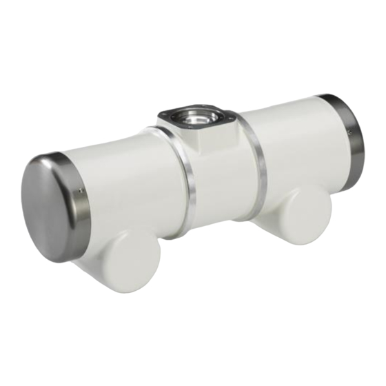
- Page 1 X-Ray tube assembly RAY-14 family Manual – Technical Description siemens-healthineers.com...
-
Page 2: Table Of Contents
Table of contents General data Validity of this document Safekeeping of operator manuals Names and parameters Address Laws, standards and regulations Description Intended purpose Functional Characteristic 4.2.1 Design 4.2.2 Characteristic Explanation of designation Notes General notes Safety information Radiation protection Operating conditions Electromagnetic Compatibility (EMC) Maintenance... - Page 3 Table of contents 7.4.1 Single loading curve 7.4.2 Series pulse mode Connection diagrams Dimensional drawings Maximum radiation field X-ray tube assembly dimensional drawings Label 10.1 The type label of the X-ray tube assembly 10.2 The type label of the X-ray tube Technical Description Print No.
- Page 4 In addition, manuals are subject to change without notice. The hardcopy documents correspond to the version at the time of system delivery and/or printout. Versions to hardcopy documentation are not automatically distributed. Please contact your local Siemens Healthineers office to order a current version or refer to our website http://www.siemens-healthineers.com. Disclaimer The contents of this document may be published under a system integrator’s/manufacturer’s label,...
-
Page 5: General Data
1 General data 1 General data Validity of this document This operator manual applies only to X-Ray tube assembly of the product RAY-14 family from Siemens Healthcare and was prepared on the basis of the applicable German and international standards, see section "Laws, standards and regulations"... -
Page 6: Address
2 Address 2 Address Siemens X-Ray Vacuum Technology Ltd., Wuxi No.112, Meiyu Road 214028 Wuxi, Jiangsu P. R. China Tel: +86-(0)510-66662888 Legal Manufacturer / Serious incident contact Fax: +86-(0)510-85345822 information * Any serious incident that has occurred in relation to the device should be reported to the manufacturer and the competent authority of the Member State in which the user and/or patient is established. -
Page 7: Laws, Standards And Regulations
3 Laws, standards and regulations 3 Laws, standards and regulations This product has been manufactured and developed in agreement with the following laws, directives and design regulations. EU Regulation 2017/745 of April 5, 2017 on medical devices (CE marking) ➢ Council Directive 2011/65/ EU of June 08, 2011 on the restriction of the use of certain hazardous ➢... -
Page 8: Description
4 Description 4 Description Intended Purpose Statement under the European Medical Device Regulation 2017/745: X-ray tube assembly intended to be integrated into X-ray imaging systems for medical purposes Intended purpose This X-ray tube housing assemblies consists of a metallic (e.g. steel, aluminumalloy) case that houses an X-ray tube to provide appropriate limits for X-ray leakage and adequate insulation to avoid electric risks during a diagnostic X-ray procedure. -
Page 9: Functional Characteristic
4 Description Undesirable side-effects Since an X-ray tube housing assembly which is not integrated in a system has no clinical effect, it consequently has no ide-effects either. Clinical effects and also side-effects are depending on the design and intended use of the diagnostic X-ray system in which the X-ray tube housing assembly is integrated and need to be determined on the system level. -
Page 10: Notes
5 Notes Rated power of large focus F2: 78 kW (Rapid) rotary frequency 150/180 Hz Siemens adapter 5 Notes General notes In the interest of complying with respected legal requirements concerning the environmental compatibility of our products (protection of natural resources, avoidance of waste) we endeavor to reuse components and to return them to the production cycle. - Page 11 5 Notes WARNING Symbols not legible or damaged may cause wrong installation. Risk of serious injuries or death due to wrong installation! • Use of the X-ray tube assembly is forbidden if signs of mechanical, electrical or radiation- related are not legible or damaged. Use of the X-ray tube assembly is forbidden if related signs are not legible or damaged.
-
Page 12: Radiation Protection
5 Notes Prior to an examination as the user’s responsibility to ensure that all safety features are functional and that the product is ready for operation. Operation of X-ray tube assembly must be terminated instantly when defect detected and notice customer service personnel immediately. -
Page 13: Electromagnetic Compatibility (Emc)
5 Notes after prolonged downtime (more than 2 weeks) for the start-up with a cold anode) Switch on fluoroscopy at 40 kV. Power up to 110 kV/2 mA within 5 minutes and hold for 10 minutes. 5 minutes cooling pause! Continue with exposure mode! 2. -
Page 14: Visual Check With The Generator Turned Off
5 Notes 5.7.1 Visual check with the generator turned off · Check the X-ray tube assembly for external damage. · Check all exposed cables to the X-ray tube assembly to ensure that the outer insulation is undamaged – do not touch during operation! ·... -
Page 15: Radiation Outlet Block
5 Notes 5.9.1 Radiation outlet block RAY-14_3 RAY-14_1 RAY-14S_3 RAY-14S_1 RAY-14S_3F The permissible weight for all components that are mounted on the radiation outlet block may together not exceed 300 N. Technical Description Print No. R76-020.140.96.15.02... -
Page 16: X-Ray Tube Assembly Connection Plates
5 Notes Flange relevant information referred to Section 9. Dimension in mm High-voltage connector on the cathode side High-voltage connector on the anode side WARNING Breakage of the radiation outlet block may caused by mechanical load too high. Risk of Physical Injury due to falling components! •... - Page 17 5 Notes RAY-14_3 RAY-14_1 See also Section 8 "Connection diagrams" • Connection of the signal cable to the temperature switches with a flat plug 6.3x0.8 suitable for the cable cross-section used. • Connection of the protective conductor cable with a cable lug (closed) suitable for Note the cable cross-section used and for M5 screw.
-
Page 18: High-Voltage Connections
5 Notes Stator key values 3-phase stator RAY-14_3 RAY-14S_3 RAY-14S_3F Test point 0 - I 0 - II I - II 22.8...24.8 22.8...24.8 22.8...24.8 Winding resistance Max. permissible operating voltage (run-up) 400V +10% Braking voltage 70 V DC Run-up time (depending on starter system) approx. -
Page 19: Tube Assembly Filtration
5 Notes S / I = Small focal spot S / I L / II L / II = Large focal spot C / 0 C / 0 = Neutral conductor Guide groove 5.9.4 Tube assembly filtration The total tube assembly filtration is 2.5mm Al equivalent and it is including additional filtration. Guide groove The added filters consist of three filter disks (3x 0.5mm Al). -
Page 20: Pictograms
5 Notes CAUTION A contact with unprotected lead is possible during the replacement of the filter plates. The inside of the protection cone in the radiate exit window is unpainted. Risk of contamination in case of skin contact with lead! •... -
Page 21: Symbol For Compliance To Ul-Standard
5 Notes CAUTION Misunderstanding of those symbols may cause wrong installation. Risk of person injury or system damage due to wrong installation! • All symbols must be fully understood. 5.10.5 Symbol for compliance to UL-standard Medical –Applied electromagnetic radiation equipment as to electric shock, fire and mechanical hazards only in accordance with ANSI/AAMI ES60601-1 (2005) + AMD 1 (2012), CAN/CSA-C22.2 No. -
Page 22: Technical Data
6 Technical Data 6 Technical Data X-ray tube / tube assembly Property Specification Standard Anode rotary Nominal input power(s) of the anode at frequency thermal anode reference power 300 W IEC 60613:1989 For anode rotary frequency 50/60 Hz 22 kW 54 kW 50 Hz / 60 Hz / 150 Hz / 180 Hz 150/180 Hz... - Page 23 6 Technical Data Property Specification Standard Heat storage capacity of the X-ray tube 1 000 kJ = 1 350 kHU IEC 60613:1989 assembly See figure in section Heating Heating and cooling curve of the X-ray tube and cooling cur ves of X-ray tube IEC 60613:1989 assembly assembly...
-
Page 24: Conditions For Operation, Storage And Transport
6 Technical Data Property Specification Standard Data on anode drive 150/180Hz( 8500 to 10800 Anode rotary frequency rpm) n.a. Exposure Fluoroscopy at 110kV 20/30Hz( 1200 to 1800 rpm) Maximum anode frequency 180 Hz n.a. See connection wiring diagram section Connection diagrams n.a. -
Page 25: Curves
7 Curves 7 Curves Heating and cooling curve of anode IEC 60613:1989 Heating and Cooling Curves of X-ray tube assembly 7.2.1 Tube assembly without fan X-ray tube assembly in horizontal position X-ray tube assembly only in vertical position Position changed during operation Technical Description Print No. -
Page 26: Tube Assembly With Fan
7 Curves IEC 60613:1989 The heating curves include the power loss of the cathode and the stator, e.g. 150/180 Hz anode drive 5000J/start-up and deceleration, 25 Hz anode drive for fluoroscopy 75 J/s. 7.2.2 Tube assembly with fan Tube assembly with fan horizontal or tube assembly vertical with fan on top IEC 60613:1989 The heating curves include the power loss of the cathode and the stator, e.g. -
Page 27: Emission Curves Of The Cathode
7 Curves Emission curves of the cathode IEC 60613:2010 IEC 60613:2010 Technical Description Print No. R76-020.140.96.15.02... -
Page 28: Loading Curves
7 Curves Loading curves 7.4.1 Single loading curve Anode drive 50/60Hz Thermal anode reference power 300W IEC 60613:1989 IEC 60613:2010 Technical Description Print No. R76-020.140.96.15.02... - Page 29 7 Curves Anode drive 50/60Hz Thermal anode reference power 300W IEC 60613:1989 IEC 60613:2010 Technical Description Print No. R76-020.140.96.15.02...
- Page 30 7 Curves Anode drive 150/180Hz Thermal anode reference power 300W IEC 60613:1989 IEC 60613:2010 Technical Description Print No. R76-020.140.96.15.02...
- Page 31 7 Curves Anode drive 150/180Hz Thermal anode reference power 300W IEC 60613:1989 IEC 60613:2010 Technical Description Print No. R76-020.140.96.15.02...
-
Page 32: Series Pulse Mode
7 Curves 7.4.2 Series pulse mode 7.4.2.1 Series pulse mode with focal spot 0.6 Anode drive 50/60 Hz Thermal anode reference power 300W IEC 60613:2010 Series duration IEC 60613:1989 Series duration Technical Description Print No. R76-020.140.96.15.02... - Page 33 7 Curves Anode drive 150/180 Hz Thermal anode reference power 300W IEC 60613:2010 Series duration IEC 60613:1989 Series duration Technical Description Print No. R76-020.140.96.15.02...
- Page 34 7 Curves 7.4.2.2 Series pulse mode with focal spot 1.2 Anode drive 50/60 Hz Thermal anode reference power 300W IEC 60613:2010 Series duration IEC 60613:1989 Series duration Technical Description Print No. R76-020.140.96.15.02...
- Page 35 7 Curves Anode drive 150/180 Hz Thermal anode reference power 300W IEC 60613:2010 Series duration IEC 60613:1989 Series duration Technical Description Print No. R76-020.140.96.15.02...
-
Page 36: Connection Diagrams
8 Connection diagrams 8 Connection diagrams RAY-14_3 RAY-14S_3 RAY-14S_3F RAY-14S_1 RAY-14_1 Technical Description Print No. R76-020.140.96.15.02... -
Page 37: Dimensional Drawings
9 Dimensional drawings 9 Dimensional drawings Maximum radiation field The field coverage depends on the source-image distance (SID) and the anode angle. For example, field coverage of 42cm x 42cm can be achieved at 1 m SID with this tube assembly (12° anode angle) Technical Description Print No. -
Page 38: X-Ray Tube Assembly Dimensional Drawings
9 Dimensional drawings X-ray tube assembly dimensional drawings RAY-14_3 RAY-14_1 RAY-14S_3 RAY-14S_1 RAY-14S_3F Technical Description Print No. R76-020.140.96.15.02... - Page 39 9 Dimensional drawings F = focus position Ref. = reference axis High-voltage connector on the cathode side High-voltage connector on the anode side Dimension in mm. All dimensions are estimated values. Technical Description Print No. R76-020.140.96.15.02...
-
Page 40: Label
10 Label 10 Label 10.1 The type label of the X-ray tube assembly The type label of the X-ray tube assembly is described in the following figure: (11) 1. Product name 2. Global Trade Identification Number 3. Model number 4. Country of Origin code 5. -
Page 41: The Type Label Of The X-Ray Tube
10 Label 10.2 The type label of the X-ray tube The type label of the X-ray tube is described in the following figure: 1. Product name 2. Global Trade Identification Number 3. Model number 4. Country of Origin code 5. Serial number 6. - Page 42 Siemens Healthineers Headquarters Legal Manufacturer Siemens Healthcare GmbH Siemens X-Ray Vacuum Henkestr. 127 TechnologyLtd., Wuxi 91052 Erlangen, Germany No.112, Meiyu Road Phone: +49 9131 84-0 214028 Wuxi, Jiangsu siemens-healthineers.com P.R. China Contact Information EU Authorized Representative according to EU Medical Device Siemens Healthcare GmbH...
Need help?
Do you have a question about the RAY-14 Series and is the answer not in the manual?
Questions and answers