Table of Contents
Advertisement
Quick Links
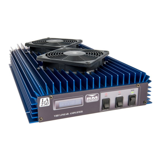
LA 251 / V
VHF 150—160 MHz Linear Amplifier
Specifications:
Operation Frequency:
Modulation Types:
Transistor:
Power Supply:
Input Fuse (Internal):
Input RF Power:
Output RF Power:
Maximum bypass power (Amplifier off): 50W
Input VSWR:
Output VSWR Maximum:
WARNING:
Before using this product please read carefully all of
the information in this manual or at least the quick start guide!!! To avoid dam-
age or incorrect operation this is extremely important!!!
150—160 MHz
SSB,CW,AM, FM, data etc (All narrowband modes)
4x Mitsubishi RD70HVF1
13VDC+/- 1V 40A
3x10A (5x20mm Fast)
1-20W (All modes)
170W @1dB Gain Compression
1.1—1.5:1
2.5:1
Reverse Polarity, High Temperature, Load VSWR
and Excessive I/P power
Quick Start Guide:
A more complete guide to the installation is featured later
1.
Connect the input RTX connector to transceiver with 50 Ohm patch
cable
2.
Connect the ANT Output of the Amplifier to SWR Bridge / Wattmeter
(If required), and then the Antenna (50 Ohm load Impedance)
3.
Connect the Amplifier DC power Cable to a suitable 13VDC (± 1V)
Power Supply or Auto Battery. Pay attention to the correct polarity
4.
Connect PTT cable if required to the transceivers PTT OUTPUT,
(The Amplifier may be used without this connected, however con-
nection is recommended for SSB operation. PTT is Active Low )
5.
Make sure that the amplifier is switched off
6.
Adjust the Transceivers RF output power to 10W (15W max) if it is
capable of more than 10W output
7.
Switch on the Amplifier and start operating
8.
Check that the antenna VSWR is acceptable with the amplifier in
use. Any large increase in VSWR indicates that the Antenna is not
suitable for the power being used. Operation should be halted im-
mediately to avoid damage to the Amplifier / Radio / ATU etc.
Advertisement
Table of Contents

Related Manuals for RM Italy LA 251/V


Summary of Contents for RM Italy LA 251/V
- Page 1 Quick Start Guide: LA 251 / V VHF 150—160 MHz Linear Amplifier A more complete guide to the installation is featured later Connect the input RTX connector to transceiver with 50 Ohm patch cable Connect the ANT Output of the Amplifier to SWR Bridge / Wattmeter (If required), and then the Antenna (50 Ohm load Impedance) Connect the Amplifier DC power Cable to a suitable 13VDC (±...
- Page 2 Installation: Front / Rear Panel Description Unpack the amplifier from it‟s shipping carton and inspect for any signs of damage. The ampli- fier should be installed (either fixed or mobile installation), in a place that allows good ventila- tion and provides a suitable base to support it. Failure to allow for reasonable ventilation will cause the amplifier to overheat and shutdown prematurely.
- Page 3 The cross sectional area of the cables used to connect the amplifier to the PSU should not be The protection circuit for excessive input power should not be regarded as a 100% protection ² for all levels of input power. Up to about 50W the circuit will work very effectively and will less than 6mm or 10 AWG They should also be kept as short as practicably possible to avoid...
- Page 4 should be less than 1.5:1. Less than 2.0:1 is acceptable but some reduction in power may be Protection: seen and the amplifier will work less efficiently and generate more heat. At about 2.0:1 the am- Excessive Heat sink temperature: plifier will signal an alarm by flashing the Alarm LED ( front panel) and when the VSWR 5 short beeps LED ( front panel) ON...
- Page 5 Warranty: This product is covered by a 24 month warranty commencing from the date of purchase. The original purchase receipt will be required for any claim. This warranty does not cover aesthetic damage or damage to the RF power transistors from incorrect use. www.rmitaly.com e-mail: Info@RMItaly.com...
Need help?
Do you have a question about the LA 251/V and is the answer not in the manual?
Questions and answers