Table of Contents
Advertisement
Advertisement
Table of Contents

Related Manuals for Honeywell VERSAFLOW MAG 4000


Summary of Contents for Honeywell VERSAFLOW MAG 4000
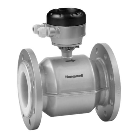
- Page 1 VERSAFLOW MAG 4000 VERSAFLOW MAG 4000 VERSAFLOW MAG 4000 VERSAFLOW MAG 4000 Quick Start Quick Start Quick Start Quick Start Electromagnetic flow sensor The documentation is only complete when used in combination with the relevant documentation for the signal converter.
-
Page 2: Table Of Contents
CONTENTS VERSAFLOW MAG 4000 1 Safety instructions 2 Installation 2.1 Scope of delivery....................... 6 2.2 Device description ......................7 2.3 Nameplate ........................8 2.4 Storage ..........................9 2.5 Transport .......................... 9 2.6 Pre-installation requirements ..................9 2.7 General requirements ....................10 2.7.1 Vibrations .......................... - Page 3 CONTENTS VERSAFLOW MAG 4000 34-VF-25-51 iss.4 GLO May 18 US www.honeywellprocess.com...
-
Page 4: Safety Instructions
SAFETY INSTRUCTIONS VERSAFLOW MAG 4000 Warnings and symbols used DANGER! This information refers to the immediate danger when working with electricity. DANGER! These warnings must be observed without fail. Even partial disregard of this warning can lead to serious health problems and even death. There is also the risk of seriously damaging the device or parts of the operator's plant. - Page 5 SAFETY INSTRUCTIONS VERSAFLOW MAG 4000 34-VF-25-51 iss.4 GLO May 18 US www.honeywellprocess.com...
-
Page 6: Installation
INSTALLATION VERSAFLOW MAG 4000 2.1 Scope of delivery INFORMATION! Do a check of the packing list to make sure that you have all the elements given in the order. INFORMATION! Inspect the packaging carefully for damages or signs of rough handling. Report damage to the carrier and to the local office of the manufacturer. -
Page 7: Device Description
INSTALLATION VERSAFLOW MAG 4000 2.2 Device description Your measuring device is supplied ready for operation. The factory settings for the operating data have been made in accordance with your order specifications. The following versions are available: • Compact version (the signal converter is mounted directly on the flow sensor) •... -
Page 8: Nameplate
INSTALLATION VERSAFLOW MAG 4000 2.3 Nameplate INFORMATION! Check the device nameplate to ensure that the device is delivered according to your order. Additional information (e.g. correct supply voltage), can be found in the documentation of the signal converter. 1 Name and address of the manufacturer... -
Page 9: Storage
INSTALLATION VERSAFLOW MAG 4000 2.4 Storage • Store the device in a dry and dust-free location. • Avoid lasting direct exposure to the sun. • Store the device in its original packaging. • Storage temperature: -50...+70°C / -58...+158°F 2.5 Transport Signal converter •... -
Page 10: General Requirements
INSTALLATION VERSAFLOW MAG 4000 2.7 General requirements INFORMATION! The following precautions must be taken to ensure reliable installation. Make sure that there is adequate space to the sides. • • Protect the signal converter from direct sunlight and install a sun shade if necessary. -
Page 11: Installation Conditions
INSTALLATION VERSAFLOW MAG 4000 2.8 Installation conditions 2.8.1 Inlet and outlet Figure 2-6: Recommended inlet and outlet 1 Refer to chapter "Bends in 2 or 3 dimensions" 2 DN INFORMATION! Sensors of type VN02 up to DN10: The inlet and outlet sections are enclosed inside the sensor. -
Page 12: T-Section
INSTALLATION VERSAFLOW MAG 4000 2.8.3 T-section Figure 2-8: Distance behind a T-section 10 DN 2.8.4 Bends Figure 2-9: Installation in bending pipes Figure 2-10: Installation in bending pipes CAUTION! Avoid draining or partial filling of the flow sensor www.honeywellprocess.com 34-VF-25-51 iss.4 GLO May 18 US... -
Page 13: Open Discharge
INSTALLATION VERSAFLOW MAG 4000 2.8.5 Open discharge Figure 2-11: Installation in front of an open discharge 2.8.6 Flange deviation CAUTION! Max. permissible deviation of pipe flange faces: 0.5 mm / 0.02" Figure 2-12: Flange deviation 2.8.7 Pump Figure 2-13: Installation behind a pump 34-VF-25-51 iss.4 GLO May 18 US... -
Page 14: Control Valve
INSTALLATION VERSAFLOW MAG 4000 2.8.8 Control valve Figure 2-14: Installation in front of a control valve 2.8.9 Air venting and vacuum forces Figure 2-15: Air venting 2 Air ventilation point Figure 2-16: Vacuum www.honeywellprocess.com 34-VF-25-51 iss.4 GLO May 18 US... -
Page 15: Mounting Position
INSTALLATION VERSAFLOW MAG 4000 2.8.10 Mounting position Figure 2-17: Mounting position • Install flow sensor in line with the pipe axis. • Pipe flange faces must be parallel to each other. 34-VF-25-51 iss.4 GLO May 18 US www.honeywellprocess.com... -
Page 16: Mounting
INSTALLATION VERSAFLOW MAG 4000 2.9 Mounting CAUTION! Please take care to use the proper gasket to prevent damaging the liner of the flowmeter. In general, the use of spiral wound gaskets is not advised, as it could severely damage the liner of the flowmeter. - Page 17 INSTALLATION VERSAFLOW MAG 4000 Nominal Pressure Bolts 2 Max. torque [Nm] 1 size rating PTFE ETFE Hard Soft DN [mm] rubber rubber PN 40 4 x M 12 PN 40 4 x M 12 PN 40 4 x M 12...
- Page 18 INSTALLATION VERSAFLOW MAG 4000 Nominal Flange Bolts 2 Max. torque [in-lb] 1 size class PTFE ETFE Hard Soft [inch] [lb] rubber rubber 1/10 4 x 1/2" 4 x 1/2" 4 x 1/2" 4 x 1/2" 4 x 1/2" 4 x 1/2"...
-
Page 19: Temperatures
INSTALLATION VERSAFLOW MAG 4000 2.9.2 Temperatures CAUTION! Protect the device from direct sunlight. Temperature range Process [°C] Ambient [°C] Process [°F] Ambient [°F] min. max. min. max. min. max. min. max. PTFE & PFA Separate flow sensor Compact with TWM 9000... -
Page 20: Electrical Connections
ELECTRICAL CONNECTIONS VERSAFLOW MAG 4000 3.1 Safety instructions DANGER! All work on the electrical connections may only be carried out with the power disconnected. Take note of the voltage data on the nameplate! DANGER! Observe the national regulations for electrical installations! DANGER! For devices used in hazardous areas, additional safety notes apply;... - Page 21 ELECTRICAL CONNECTIONS VERSAFLOW MAG 4000 Figure 3-2: Different types of grounding rings 1 Grounding ring number 1 2 Grounding ring number 2 3 Grounding ring number 3 Grounding ring number 1: • Thickness : 3 mm / 0.1" (tantalum: 0.5 mm / 0.02") Grounding ring number 2: •...
-
Page 22: Virtual Reference For Twm 9000 (C, W And F Version)
ELECTRICAL CONNECTIONS VERSAFLOW MAG 4000 3.3 Virtual reference for TWM 9000 (C, W and F version) Figure 3-3: Virtual reference Minimum requirements: • Size: DN10 / 3/8" • Electrical conductivity: 200 μS/cm • Signal cable: max. 50 m / 164 ft, type DS 3.4 Connection diagrams... - Page 23 ELECTRICAL CONNECTIONS VERSAFLOW MAG 4000 34-VF-25-51 iss.4 GLO May 18 US www.honeywellprocess.com...
-
Page 24: Technical Data
TECHNICAL DATA VERSAFLOW MAG 4000 4.1 Dimensions and weights Remote version Remote version Remote version Remote version a = 88 mm / 3.5" b = 139 mm / 5.5" c = 106 mm / 4.2" Total height = H + a... - Page 25 TECHNICAL DATA VERSAFLOW MAG 4000 EN 1092-1 Nominal size Dimensions [mm] Approximately weight [kg] PN [bar] ISO 13359 2.5...6 1012 1015 1114 1115 1000 1000 1225 1230 1200 1200 1417 1405 1400 1400 1619 1630 1600 1600 1819 1830 1035...
- Page 26 TECHNICAL DATA VERSAFLOW MAG 4000 150 lb flanges Nominal size Dimensions [inch] Approximately weight [lb] ASME PN [psi] ISO 13359 1/10" 5.12 5.59 3.50 1/8" 5.12 5.59 3.50 ¼" 5.12 5.59 3.50 3/8" 5.12 5.08 3.50 ½" 5.12 7.87 5.08 3.50...
- Page 27 TECHNICAL DATA VERSAFLOW MAG 4000 300 lb flanges Nominal size Dimensions [inch] Approximately weight [lb] ASME PN [psi] ISO 13359 1/10" 5.12 5.59 3.75 1/8" 5.12 5.59 3.75 ¼" 5.12 5.59 3.75 3/8" 5.12 5.24 3.75 ½" 5.12 7.87 5.24 3.75...
-
Page 28: Vacuum Load
TECHNICAL DATA VERSAFLOW MAG 4000 4.2 Vacuum load Diameter Max. Vacuum load in mbar abs. at a process temperature of pressure [mm] [bar] 40°C 60°C 70°C 80°C 90°C 100°C 120°C 140°C 180°C Liner in PTFE Liner in PTFE Liner in PTFE Liner in PTFE DN10...20... -
Page 29: Technical Data
TECHNICAL DATA VERSAFLOW MAG 4000 34-VF-25-51 iss.4 GLO May 18 US www.honeywellprocess.com... - Page 30 Houston, TX 77042 Houston, TX 77042 www.honeywellprocess.com www.honeywellprocess.com www.honeywellprocess.com www.honeywellprocess.com © Honeywell International Inc. © Honeywell International Inc. © Honeywell International Inc. © Honeywell International Inc. Subject to change without notice. Subject to change without notice. Subject to change without notice.
Need help?
Do you have a question about the VERSAFLOW MAG 4000 and is the answer not in the manual?
Questions and answers