
Subscribe to Our Youtube Channel
Related Manuals for RKI Instruments 35-3001-05 Series


Summary of Contents for RKI Instruments 35-3001-05 Series
- Page 1 35-3001-05-XX Carbon Dioxide Sample-Draw Detector Operator’s Manual Part Number: 71-0413 Revision: A Released: 6/20/19 www.rkiinstruments.com...
- Page 2 WARNING Read and understand this instruction manual before operating detector. Improper use of the detector could result in bodily harm or death. Periodic calibration and maintenance of the detector is essential for proper operation and correct readings. Please calibrate and maintain this detector regularly! Frequency of calibration depends upon the type of use you have and the sensor types.
- Page 3 Product Warranty RKI Instruments, Inc. warrants gas alarm equipment sold by us to be free from defects in materials, workmanship, and performance for a period of one year from date of shipment from RKI Instruments, Inc. Any parts found defective within that period will be repaired or replaced, at our option, free of charge. This warranty does not apply to those items which by their nature are subject to deterioration or consumption in normal service, and which must be cleaned, repaired, or replaced on a routine basis.
-
Page 4: Table Of Contents
Table of Contents Overview ..............5 Specifications . -
Page 5: Overview
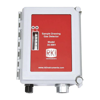
Overview This operator’s manual describes the 35-3001-05-XX carbon dioxide sample-draw detector. This manual also describes how to install, start up, maintain, and calibrate the sample-draw detector when using it with a gas monitoring controller. A parts list at the end of this manual lists replacement parts and accessories for the sample-draw detector. -
Page 6: Description
Description This section describes the components of the carbon dioxide sample-draw detector. Pump Connector Oxy gen Sensor Mounting Flowmeter Circuit Terminal Foot, 4X Board Connector Strip Sensor Flow Control V alve Pump Fail LED Pilot LED IR CO 2 Sensor (inside b lock) IR CO 2 Pump Reset... -
Page 7: External Components
External Components This section describes the sample-draw detector’s external components. Housing The sample-draw detector’s fiberglass housing is weather- and corrosion-resistant. It is suitable for installation where general purpose equipment is in use. The housing door is hinged on the left side and is secured by two latches on the right side. The flowmeter and status LEDs are visible through a window in the housing door. - Page 8 Main Circuit Board The main circuit board includes the detector/amp terminal strip, interconnect terminal strip, oxygen sensor terminal strip, pump connector, and flowmeter circuit board connector (see Figure 1). Detector/Amp Terminal Strip The detector/amp terminal strip is the upper twelve-point terminal strip in the bottom right corner of the main circuit board.
- Page 9 Status LEDs Two status LEDs are above the flowmeter. They are also visible through the window in the housing door. The green Pilot LED is on when the sample-draw detector is receiving power from the controller. The red Fail LED is on when the sample flow rate is below the low flow level. Pressure Switch The pressure switch is mounted to the back of the flowmeter circuit board.
-
Page 10: Installation
Installation This section describes procedures to mount the sample-draw detector in the monitoring environment and wire the sample-draw detector to a controller. Mounting the Carbon Dioxide Sample-Draw Detector Select the mounting site. Consider the following when you select the mounting site: •... -
Page 11: Connecting The Sample Lines To The Sample-Draw Detector
Connect a length of sample tubing to the other side of the particle filter and route it to the sampling area. 1/4” O.D. rigid polypropylene, Teflon, or flexible polyurethane tubing may be used. RKI Instruments, Inc. recommends using either 1/4” O.D. x 1/8” I.D. or 1/4” O.D. x 0.170” I.D. tubing based on your length requirements. -
Page 12: Wiring The Carbon Dioxide Sample-Draw Detector To A Controller
Push 1/4” O.D. rigid polypropylene or rigid Teflon sample tubing into the fitting until it stops. Flexible polyurethane tubing may be used with an appropriate insert. RKI Instruments, Inc. recommends using either 1/4” O.D. x 1/8” I.D. or 1/4” O.D. x 0.170” I.D. tubing based on your length requirements. See “Specifications”... - Page 13 Connect the wires to the applicable detector/transmitter terminal strip at the controller as shown in Figure 4. Refer to the controller operator’s manual and the controller detector head specification sheet for the 35-3001-05-XX for detector/terminal strip connections specific to the controller. Not Used on This Version Black...
-
Page 14: Start Up
Start Up This section describes procedures to start up the sample-draw detector and place the sample-draw detector into normal operation. Introducing Incoming Power Complete the installation procedures described earlier in this manual. Verify that the wiring is correct and secure. Refer to the controller operator’s manual for connections at the controller. -
Page 15: Maintenance
Maintenance This section describes maintenance procedures. It includes preventive maintenance procedures. This section also includes procedures to troubleshoot the sample-draw detector, replace components of the sample-draw detector, adjust the low flow setting, and remove the particle filter’s tubing stub. Preventive Maintenance This section describes a preventive maintenance schedule to ensure the optimum performance of the sample- draw detector. -
Page 16: Replacing Components Of The Carbon Dioxide Sample-Draw Detector
If the fail condition continues, replace the sensor as described in “Replacing the Infrared Carbon Dioxide Sensor” on page 16. If the fail condition continues, contact RKI Instruments, Inc. for further instruction. Slow or No Response/Difficult or Unable to Calibrate Symptoms •... - Page 17 12. Calibrate the replacement sensor as described in “Calibration” on page 20. Replacing the Hydrophobic Filter Turn off the controller. Turn off power to the controller. Open the housing door of the sample-draw detector. Disconnect the filter from the rubber elbows on each end of the filter, then remove the filter from the sample-draw detector.
-
Page 18: Adjusting The Low Flow Setting
Adjusting the Low Flow Setting NOTE: Adjusting the low flow setting will cause a low flow alarm at the sample-draw detector and a fail alarm at the controller. Be sure to put the controller into its calibration program or disable external alarms before performing this test. -
Page 19: Removing The Particle Filter's Tubing Stub, If Necessary
Removing the Particle Filter’s Tubing Stub, if Necessary A short tubing stub comes factory installed in the particle filter. It is used for connecting the particle filter to the inlet fitting. If you have installed the particle filter and no longer want it installed, you will need to remove the particle filter’s tubing stub from the inlet fitting and replace it with tubing. -
Page 20: Calibration Frequency
Although there is no particular calibration frequency that is correct for all applications, a calibration frequency of every 6 months is adequate for most infrared combustible gas transmitter applications. Unless experience in a particular application dictates otherwise, RKI Instruments, Inc. recommends a calibration frequency of every 6 months. -
Page 21: Returning To Normal Operation
Disconnect the sample tubing from the inlet line. Unscrew the regulator from the carbon dioxide calibration cylinder. Returning to Normal Operation Wait approximately one minute to allow the carbon dioxide reading to stabilize. Follow the instructions in the controller’s operator’s manual to exit the calibration mode. Store the components of the calibration kit in a safe and convenient place. - Page 22 Table 2: Parts List Part Number Description 81-0078RK-03 Calibration cylinder, 100% nitrogen, 103 liter 81-1054RK Regulator, demand flow, for 34 liter aluminum, 58 liter, and 103 liter cali- bration cylinders (cylinders with internal threads) 81-1055RK Regulator, demand flow, for 17 liter and 34 liter steel calibration cylinders (cylinders with external threads) 22 •...
Need help?
Do you have a question about the 35-3001-05 Series and is the answer not in the manual?
Questions and answers