
Related Manuals for RKI Instruments 35-3001A-01 1 Series


Summary of Contents for RKI Instruments 35-3001A-01 1 Series
- Page 1 35-3001A-01-XX1 Sample-Draw Detector Operator’s Manual Part Number: 71-0585 Revision: P1 Released: 1/25/22 www.rkiinstruments.com...
- Page 2 WARNING Read and understand this instruction manual before operating detector. Improper use of the detector could result in bodily harm or death. Periodic calibration and maintenance of the detector is essential for proper operation and correct readings. Please calibrate and maintain this detector regularly! Frequency of calibration depends upon the type of use you have and the sensor types.
- Page 3 Product Warranty RKI Instruments, Inc. warrants gas alarm equipment sold by us to be free from defects in materials, workmanship, and performance for a period of one year from date of shipment from RKI Instruments, Inc. Any parts found defective within that period will be repaired or replaced, at our option, free of charge.
-
Page 4: Table Of Contents
Table of Contents Overview ..............5 Specifications . -
Page 5: Overview
Overview This operator’s manual describes the 35-3001A-01-XX1 sample-draw detector. This version of the sample-draw detector has low flow contacts that allow the user to monitor the detector’s low flow status. This manual also describes how to install, start up, maintain, and calibrate the sample-draw detector when using it with a gas monitoring controller. - Page 6 Table 1:Specifications Inlet Exhaust Maximum Recommended Inlet/Exhaust Line Length 100 feet 100 feet for 1/4” O.D. x 0.170” I.D. Tubing 90% in 30 seconds Response Time ± 5% of reading or ± 2% of full scale (whichever is greater) Accuracy WARNING: When using the 35-3001A-01-XX1, you must follow the instructions and warnings in this manual to assure proper and safe operation of the 35-3001A- 01-XX1 and to minimize the risk of personal injury.
-
Page 7: Description
Description This section describes the components of the sample-draw detector. Pump Connector Mounting Foot, 4X Flowmeter Circuit IR Amplifier Board Connector Oxygen Sensor Terminal Sensor Flow Sensor Strip Control Valve Current 148mA Pump Fail LED Pilot LED PWR / SIG IR Sensor (inside block) IR Flow Block... -
Page 8: External Components
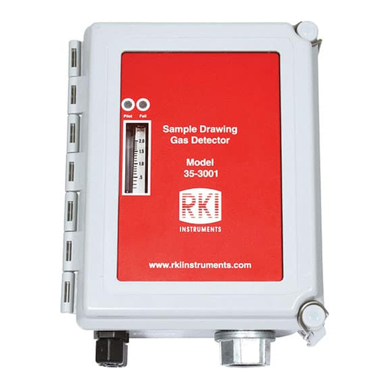
External Components This section describes the sample-draw detector’s external components. Housing The sample-draw detector’s fiberglass housing is weather- and corrosion-resistant. It is suitable for installation where general purpose equipment is in use. The housing door is hinged on the left side and is secured by two latches on the right side. The flowmeter and status LEDs are visible through a window in the housing door. -
Page 9: Internal Components
Internal Components This section describes the sample-draw detector’s internal components (see Figure 1). Figure 2 illustrates how the gas sample moves through the flow system. Pressure Switch Flowmeter Exhaust Sensor Flowmeter PCB Sensor Flow Control Restrictor Valve Inlet Pump Particle Filter Hydrophobic Filter Figure 2: Sample-Draw Detector Flow Diagram Main Circuit Board... - Page 10 Pump Connector The pump connector is the two-point connector below the oxygen terminal strip in the upper right corner of the main circuit board. Use the pump connector to connect the pump to the main circuit board. NOTE: The pump is factory-wired to the main circuit board. See “Installation” on page 12 for all wiring procedures related to the sample-draw detector.
- Page 11 If the flow rate falls below the preset low flow level, the pressure switch causes the Fail LED to turn on and interrupts the signal from the detector. The interrupted detector signal causes a fail condition at the controller. The low flow level is factory-set at 0.6 SCFH (±0.1 SCFH). See “Adjusting the Low Flow Setting”...
-
Page 12: Installation
Zero Pot The zero pot is located in the upper right corner of the amplifier (see Figure 3). Use a small flat blade screwdriver to turn the zero pot’s adjustment screw and adjust the amplifier’s zero (fresh air) output during the start-up and calibration procedures. Turn the adjustment screw clockwise to increase the fresh air output and counterclockwise to decrease the fresh air output. - Page 13 6.50 Ø .30 x .50 (4X) M OUNTING 1.13 4.00 Pilot Fail Sample Drawing Gas Detector 8.88 8.50 35-3001 www.rkiinstruments.com 4.50 NOTE: Housing is 4.3 inches deep Figure 4: Outline and Mounting Dimensions 2. Close and latch the housing door. NOTE: The sample-draw detector is shipped with the mounting feet “tucked under”...
-
Page 14: Connecting The Sample Lines To The Sample-Draw Detector
1/4” O.D. rigid polypropylene, Teflon, or flexible polyurethane tubing may be used. RKI Instruments, Inc. recommends using either 1/4” O.D. x 1/8” I.D. or 1/4” O.D. x 0.170” I.D. tubing based on your length requirements. See “Specifications” on page 5 for maximum tubing lengths based on tubing size. -
Page 15: Wiring The Sample-Draw Detector To A Controller
CAUTION: Avoid loops or slumps in the incoming sample line. To reduce response time, keep the incoming sample line as short as possible. 5. If desired, install the particle filter onto the end of the inlet line. Be sure the arrow on the particle filter is pointed toward the inlet line. - Page 16 CAUTION: If using shielded cable, leave the cable shield’s drain wire insulated and disconnected at the sample-draw detector. You will connect the opposite end of the drain wire at the controller. 7. Route the cable or wires in conduit leading from the sample-draw detector through one of the conduit hubs at the controller.
- Page 17 Not Used on This Version Sensor ZERO Current 148mA SPAN PWR / SIG W hite Green Black IR Sensor AMP 1 AM P 2 FLO W FAIL Low Flow Relay Contact Ratings: 125 VAC 0.6A IR Sensor 30 VDC 1A FLO W 110 VDC 0.6A AM P 1...
-
Page 18: Start Up
Start Up This section describes procedures to start up the sample-draw detector and place the sample- draw detector into normal operation. Introducing Incoming Power 1. Complete the installation procedures described earlier in this manual. 2. Verify that the wiring is correct and secure. Refer to the controller operator’s manual for connections at the controller. -
Page 19: Setting The Zero Reading
Setting the Zero Reading CAUTION: If you suspect the presence of combustible gas in the monitoring environment, use the calibration kit and the zero air calibration cylinder to introduce “fresh air” to the sensor and verify an accurate zero setting. See “Calibration” on page 26 for instructions on using a zero air calibration cylinder for setting the zero reading. -
Page 20: Maintenance
Maintenance This section describes maintenance procedures. It includes preventive maintenance procedures. This section also includes procedures to troubleshoot the sample-draw detector, replace components of the sample-draw detector, adjust the low flow setting, and remove the particle filter’s tubing stub. Preventive Maintenance This section describes a preventive maintenance schedule to ensure the optimum performance of the sample-draw detector. - Page 21 5. If the fail condition continues, replace the sensor as described in “Replacing the Infrared Sensor” on page 22. 6. If the fail condition continues, contact RKI Instruments, Inc. for further instruction. Slow or No Response/Difficult or Unable to Calibrate Symptoms •...
-
Page 22: Replacing Components Of The Sample-Draw Detector
Replacing Components of the Sample-Draw Detector This section includes procedures to replace the sensor, hydrophobic filter, and particle filter. Replacing the Infrared Sensor 1. Turn off the controller. 2. Turn off power to the controller. 3. Open the housing door of the sample-draw detector. 4. - Page 23 9. Install the detector and controller plug-in terminals strips into their sockets on the new amplifier. If controller leads or detector cable leads were removed from the plug-in terminal strips during this procedure, refer to Table 3 and Table 4 below. Table 3: Reconnecting the Amplifier to the Detector/Amp Terminal Strip Amplifier Controller Detector/Amp Terminal...
-
Page 24: Adjusting The Low Flow Setting
5. Install the new filter. Be sure the side of the filter marked “INLET” is connected to the elbow that is connected to the inlet fitting. 6. Turn on power to the controller. 7. Turn on the controller. 8. Verify that the flow rate is approximately 1.0 SCFH, then close the housing door. Replacing the Particle Filter 1. -
Page 25: Removing The Particle Filter's Tubing Stub, If Necessary
2. Slowly turn the pressure switch adjustment screw counterclockwise just until the sample- draw detector goes into low flow alarm. 3. Turn the sensor flow control valve’s knob counterclockwise to increase the flow until the unit is out of low flow alarm when the reset switch is pressed and released. 4. -
Page 26: Calibration Frequency
1. Remove the particle filter from its tubing stub. 2. Unscrew the outside inlet fitting tube nut from the fitting body. The tubing stub should come out with the tube nut. Be careful not to lose the O-ring that may come out with the tubing stub. -
Page 27: Setting The Zero Reading
2. Screw the regulator into a zero air calibration cylinder. 3. Open the housing door. 4. Set a voltmeter to measure in the millivolt (mV) range. 5. Plug the positive lead into the red (+) amplifier test point; plug the negative lead into the black (-) amplifier test point labeled. -
Page 28: Returning To Normal Operation
Returning to Normal Operation 1. Wait approximately one minute to allow the reading to stabilize. 2. Remove the voltmeter leads from the amplifier test points. 3. Close the housing door. 4. Follow the instructions in the controller’s operator’s manual to exit the calibration mode. 5. -
Page 29: Parts List
Parts List Table 5 lists replacement parts and accessories for the sample-draw detector. Table 5: Parts List Part Number Description 06-1248RK Sample tubing, 3/16 in. ID x 5/16 in. OD, specify length 06-1248RK-03 Sample tubing, 3/16 in. ID x 5/16 in. OD, 3 feet (for calibration kit) 07-0110RK Gasket for IR flow block 17-2670...
Need help?
Do you have a question about the 35-3001A-01 1 Series and is the answer not in the manual?
Questions and answers