
Related Manuals for RKI Instruments 35-3001-06H-DIL


Summary of Contents for RKI Instruments 35-3001-06H-DIL
- Page 1 35-3001-06H-DIL Hydrogen/Oxygen Sample-Draw Detector Operator’s Manual Part Number: 71-0346 Revision: A Released: 8/7/17 www.rkiinstruments.com...
- Page 2 Typical calibration frequencies for most applications are between 3 and 6 months, but can be required more often or less often based on your usage. 35-3001-06H-DIL Hydrogen/Oxygen Sample-Draw Detector...
- Page 3 Product Warranty RKI Instruments, Inc. warrants gas alarm equipment sold by us to be free from defects in materials, workmanship, and performance for a period of one year from date of shipment from RKI Instruments, Inc. Any parts found defective within that period will be repaired or replaced, at our option, free of charge.
-
Page 4: Table Of Contents
Parts List ..............23 35-3001-06H-DIL Hydrogen/Oxygen Sample-Draw Detector... -
Page 5: Overview
About the 35-3001-06H-DIL The 35-3001-06H-DIL is designed to monitor hydrogen and oxygen in an inerted area (an area that has no, or almost no, oxygen present). The catalytic LEL sensor used to detect hydrogen must have at least 5% oxygen present to detect gas properly. - Page 6 ± 0.5% O WARNING: When using the 35-3001-06H-DIL, you must follow the instructions and warnings in this manual to assure proper and safe operation of the 35-3001-06H- DIL and to minimize the risk of personal injury. Be sure to maintain and periodically calibrate the 35-3001-06H-DIL as described in this manual.
-
Page 7: Description
AMP 1 AMP 2 Interconnect Terminal Stri p Thi s End To Inl et Fitting 3/4" Conduit Hub Particle Filter INLET Inl et Fitting EXHAUST Exhaust Fitting Figure 1: Hydrogen/Oxygen Sample-Draw Detector Component Location 35-3001-06H-DIL Hydrogen/Oxygen Sample-Draw Detector • 3... -
Page 8: External Components
Flowmeter Exhaust Pump Restrictor Flowmeter PCB Sensor Sensor Flow Control Valve Dilution Fitting, Inlet approx. 1:1 ratio Pressure Switch Oxygen Sensor Particle Filter Hydrophobic Filter Figure 2: Hydrogen/Oxygen Sample-Draw Detector Flow Diagram 4 • 35-3001-06H-DIL Hydrogen/Oxygen Sample-Draw Detector... - Page 9 A ball in the flowmeter column indicates the flow rate to the LEL sensor which is the sample flow plus the dilution flow. The oxygen sensor’s flow rate is approximately 35-3001-06H-DIL Hydrogen/Oxygen Sample-Draw Detector • 5...
- Page 10 The hydrogen sensor is installed in the flow block and the flow block is mounted to the middle of the main circuit board. It is the lower of the two flow blocks mounted to the main circuit board. An 6 • 35-3001-06H-DIL Hydrogen/Oxygen Sample-Draw Detector...
- Page 11 The pump is mounted to the right side of the main circuit board. The pump pulls the gas sample into the sample-draw detector. The pump operates on 24 VAC, which is generated from the 24 VDC supplied by the controller. 35-3001-06H-DIL Hydrogen/Oxygen Sample-Draw Detector • 7...
-
Page 12: Installation
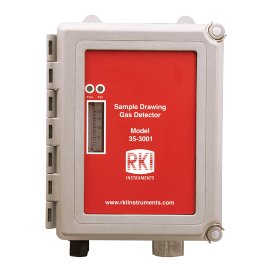
Ø .30 x .50 (4X) M OUNTING 1.13 4.00 Pilot Fail Sample Drawing Gas Detector 8.88 8.50 35-3001 www.rkiinstruments.com 4.50 NOTE: Housing is 4.3 inches deep Figure 3: Outline and Mounting Dimensions Close and latch the housing door. 8 • 35-3001-06H-DIL Hydrogen/Oxygen Sample-Draw Detector... -
Page 13: Connecting The Sample Lines To The Sample-Draw Detector
1/4” O.D. rigid polypropylene, Teflon, or flexible polyurethane tubing may be used. RKI Instruments, Inc. recommends using either 1/4” O.D. x 1/8” I.D. or 1/4” O.D. x 0.170” I.D. tubing based on your length requirements. See “Specifications” on page 1 for maximum tubing lengths based on tubing size. -
Page 14: Wiring The Sample-Draw Detector To A Controller
Push 1/4” O.D. rigid polypropylene or rigid Teflon sample tubing into the fitting until it stops. Flexible polyurethane tubing may be used with an appropriate insert. RKI Instruments, Inc. recommends using either 1/4” O.D. x 1/8” I.D. or 1/4” O.D. x 0.170” I.D. tubing based on your length requirements. - Page 15 Connect the wires to the applicable detector/transmitter terminal strip at the controller as shown in Figure 4. Refer to the controller operator’s manual and the controller detector head specification sheet for the 35-3001-06H-DIL for detector/terminal strip connections specific to the controller.
-
Page 16: Start Up
Setting the Zero Reading Since the 35-3001-06H-DIL monitors an inerted area, in order to set the zero reading, the inlet line must be moved to a fresh air area, the inlet line must be removed so that sample is being drawn through the inlet fitting (if the instrument is mounted in a fresh air area), or a zero air cylinder must be used. -
Page 17: Maintenance
If the display reading is not 0 %LEL for the hydrogen channel or 20.9% for the oxygen channel, set the zero reading as described in “Calibration, LEL Sensor” on page 19 or “Calibration, Oxygen Sensor” on page 21, then continue this procedure. 35-3001-06H-DIL Hydrogen/Oxygen Sample-Draw Detector • 13... -
Page 18: Troubleshooting
Probable causes • The sample-draw detector’s flow rate is too low because of an obstructed sample line, failed pump, etc. • The sample-draw detector is malfunctioning. • The sensor wiring is disconnected or misconnected. 14 • 35-3001-06H-DIL Hydrogen/Oxygen Sample-Draw Detector... - Page 19 Connect a 0-2 SCFH flowmeter to the inlet fitting or the inlet line and confirm the flow is above the low flow setpoint of 1 SCFH while holding down the reset switch. NOTE: RKI Instruments, Inc. offers a 0 -2 SCFH flowmeter but tubing connection fittings must be user installed to the flowmeter’s 1/8” NPT female fittings.
-
Page 20: Replacing Components Of The Sample-Draw Detector
Close and latch the housing door. 10. Turn on power to the controller. 11. Turn on the controller. CAUTION: Allow the replacement sensor to warm up for 5 minutes before you continue. 16 • 35-3001-06H-DIL Hydrogen/Oxygen Sample-Draw Detector... -
Page 21: Adjusting The Low Flow Setting
Install a 0-2 SCFH flowmeter with an adjustment valve at the inlet of the sample-draw detector. NOTE: RKI Instruments, Inc. offers a 0 - 2 SCFH flowmeter but tubing connection fittings must be user installed to the flowmeter’s 1/8” NPT female fittings. -
Page 22: Removing The Particle Filter's Tubing Stub, If Necessary
1/4" Tube Inside of C ase Outside of Case O-ring Fitting Body Back Ferrule Tube Nut Front Ferrule 1/4" Tube Figure 5: Inlet Fitting with Tubing Stub 18 • 35-3001-06H-DIL Hydrogen/Oxygen Sample-Draw Detector... -
Page 23: Calibration Frequency
Although there is no particular calibration frequency that is correct for all applications, a calibration frequency of every 3 months is adequate for most sample draw detector applications. Unless experience in a particular application dictates otherwise, RKI Instruments, Inc. recommends a calibration frequency of every 3 months. -
Page 24: Setting The Zero Reading
Wait approximately one minute to allow the hydrogen reading to stabilize. Follow the instructions in the controller’s operator’s manual to exit the calibration mode. Store the components of the calibration kit in a safe and convenient place. 20 • 35-3001-06H-DIL Hydrogen/Oxygen Sample-Draw Detector... -
Page 25: Calibration, Oxygen Sensor
Turn the regulator’s on/off knob counterclockwise to close it. Clamp the gas bag shut and disconnect it from the fixed flow regulator. Connect the gas bag tubing to the inlet line and release the clamp. 35-3001-06H-DIL Hydrogen/Oxygen Sample-Draw Detector • 21... -
Page 26: Returning To Normal Operation
NOTE: If you do not allow the oxygen reading to return to normal, then unwanted alarms may occur. Verify that the controller display reading stabilizes at 20.9%. Store the components of the calibration kit in a safe and convenient place. 22 • 35-3001-06H-DIL Hydrogen/Oxygen Sample-Draw Detector... -
Page 27: Parts List
Regulator with gauge and knob, 6 LPM, for 34 liter aluminum cylinder, 58 liter, and 103 liter cylinders (cylinders with internal threads) 81-1127RK Gas bag with fittings and hosebarb, 12 inches x 12 inches, 5 liters, tedlar OS-B11 Oxygen sensor 35-3001-06H-DIL Hydrogen/Oxygen Sample-Draw Detector • 23...
Need help?
Do you have a question about the 35-3001-06H-DIL and is the answer not in the manual?
Questions and answers