
Related Manuals for RKI Instruments 35-3001A-10


Summary of Contents for RKI Instruments 35-3001A-10
- Page 1 35-3001A-10 Oxygen/Carbon Monoxide Sample-Draw Detector Operator’s Manual Part Number: 71-0558 Revision: P1 Released: 5/3/21 www.rkiinstruments.com...
- Page 2 Typical calibration frequencies for most applications are between 3 and 6 months, but can be required more often or less often based on your usage. 2 • 35-3001A-10 Oxygen/Carbon Monoxide Sample-Draw Detector...
- Page 3 Product Warranty RKI Instruments, Inc. warrants gas alarm equipment sold by us to be free from defects in materials, workmanship, and performance for a period of one year from date of shipment from RKI Instruments, Inc. Any parts found defective within that period will be repaired or replaced, at our option, free of charge.
-
Page 4: Table Of Contents
Parts List ..............29 4 • 35-3001A-10 Oxygen/Carbon Monoxide Sample-Draw Detector... -
Page 5: Overview
Overview This operator’s manual describes the 35-3001A-10 oxygen/carbon monoxide sample-draw detector. This manual also describes how to install, start up, maintain, and calibrate the sample-draw detector when using it with a gas monitoring controller. A parts list at the end of this manual lists replacement parts and accessories for the sample-draw detector. - Page 6 WARNING: When using the 35-3001A-10, you must follow the instructions and warnings in this manual to assure proper and safe operation of the 35-3001A-10 and to minimize the risk of personal injury. Be sure to maintain and periodically calibrate the 35-3001A- 10 as described in this manual.
-
Page 7: Description
AMP 1 AMP 2 O XY LEL / IR Interconnect Terminal Strip This End T o Inlet Fitting 3/4" Conduit Hub Particle F ilter INLET Inlet Fitting EXHAUST Exhaust Fitting Figure 1: Component Location 35-3001A-10 Oxygen/Carbon Monoxide Sample-Draw Detector • 7... -
Page 8: External Components
Pressure Switch Flowmeter Exhaust Flowmeter PCB Sensor Restrictor Sensor Flow Control Valve Inlet Flow Baffle Oxygen Sensor Pump Particle Filter Hydrophobic Filter Figure 2: Flow Diagram 8 • 35-3001A-10 Oxygen/Carbon Monoxide Sample-Draw Detector... - Page 9 Use the flowmeter circuit board connector to connect the flowmeter circuit board to the main circuit board. NOTE: The flowmeter circuit board is factory wired to the main circuit board. See page 13 for wiring instructions. 35-3001A-10 Oxygen/Carbon Monoxide Sample-Draw Detector • 9...
- Page 10 The leads extending from the sensor terminate in lugs that connect to the oxygen terminal strip. 10 • 35-3001A-10 Oxygen/Carbon Monoxide Sample-Draw Detector...
- Page 11 A flow baffle is located at the bottom of the main circuit board, behind the hydrophobic filter. Its function is to isolate the carbon monoxide sensor from vibrations in the flow line that are caused by the pump. 35-3001A-10 Oxygen/Carbon Monoxide Sample-Draw Detector • 11...
- Page 12 (CAL 2) in the upper left corner is the negative (-) test point and the red test point (CAL 1) in the upper right corner is the positive (+) test point. 12 • 35-3001A-10 Oxygen/Carbon Monoxide Sample-Draw Detector...
-
Page 13: Installation
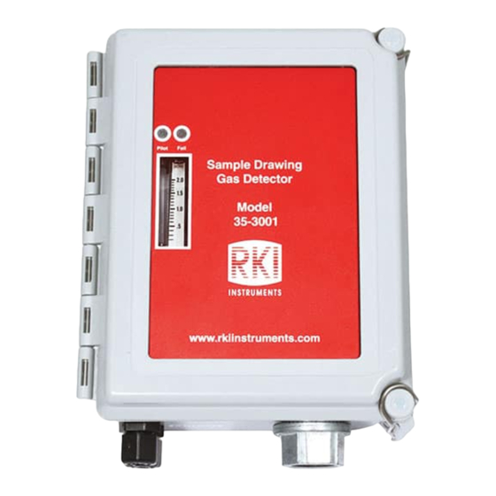
6.50 Ø .30 x .50 (4X) M OUNTING 1.13 4.00 Pilot Fail Sample Drawing Gas Detector 8.88 8.50 35-3001 www.rkiinstruments.com 4.50 NOTE: Housing is 4.3 inches deep Figure 5: Outline and Mounting Dimensions 35-3001A-10 Oxygen/Carbon Monoxide Sample-Draw Detector • 13... -
Page 14: Connecting The Sample Lines To The Sample-Draw Detector
2. Push 1/4” O.D. rigid polypropylene or rigid Teflon sample tubing into the fitting until it stops. Flexible polyurethane tubing may be used with an appropriate insert. RKI Instruments, Inc. recommends using either 1/4” O.D. x 1/8” I.D. or 1/4” O.D. x 0.170” I.D. tubing based on your length requirements. -
Page 15: Wiring The Sample-Draw Detector To A Controller
2. Push 1/4” O.D. rigid polypropylene or rigid Teflon sample tubing into the fitting until it stops. Flexible polyurethane tubing may be used with an appropriate insert. RKI Instruments, Inc. recommends using either 1/4” O.D. x 1/8” I.D. or 1/4” O.D. x 0.170” I.D. tubing based on your length requirements. - Page 16 8. Connect the wires to the applicable detector/transmitter terminal strip at the controller as shown in Figure 6. Refer to the controller operator’s manual and the controller detector head specification sheet for the 35-3001A-10 for detector/terminal strip connections specific to the controller. T OXIC...
-
Page 17: Start Up
27 for instructions on using a zero air calibration cylinder for setting the zero reading. 1. Verify that the sample-draw detector is sampling a fresh air environment (environment known to be free of toxic gas and of normal oxygen concentration, 20.9%). 2. Open the housing door. 35-3001A-10 Oxygen/Carbon Monoxide Sample-Draw Detector • 17... -
Page 18: Maintenance
3. Verify a display reading of 20.9% for the oxygen channel and 0 ppm for the CO channel at the controller. Investigate significant changes in the display reading. Quarterly Calibration Calibrate the sample-draw detector as described in “Calibration, Oxygen Sensor” on page 25 and “Calibration, CO Sensor” on page 27. 18 • 35-3001A-10 Oxygen/Carbon Monoxide Sample-Draw Detector... -
Page 19: Troubleshooting
“Calibration, CO Sensor” on page 27. 5. If the fail condition continues, replace the sensor(s) as described on page 20. 6. If the fail condition continues, contact RKI Instruments, Inc. for further instruction. Slow or No Response/Difficult or Unable to Calibrate Symptoms •... -
Page 20: Replacing Components Of The Sample-Draw Detector
4. If you cannot set the correct flow rate, check the sample line for obstructions or kinks. 5. If the calibration/response difficulties continue, replace the sensor as described later in this section. 6. If the calibration/response difficulties continue, contact RKI Instruments, Inc. for further instruction. - Page 21 AMP 1 “+” Table 3: Reconnecting the Amplifier to the Oxy Terminals on the Detector/Amp Terminal Strip Detector/Amp Amplifier Detector Terminal Strip on Terminal Strip Main PCB OXY “+” OXY “+” OXY “-” OXY “-” 35-3001A-10 Oxygen/Carbon Monoxide Sample-Draw Detector • 21...
- Page 22 2. Turn off power to the controller. 3. Open the housing door of the sample-draw detector. 4. Disconnect the filter from the rubber elbows on each end of the filter, then remove the filter from the sample-draw detector. 22 • 35-3001A-10 Oxygen/Carbon Monoxide Sample-Draw Detector...
-
Page 23: Adjusting The Low Flow Setting
3. Turn the sensor flow control valve’s knob clockwise to increase the flow until the unit is out of low flow alarm when the reset switch is pressed and released. 35-3001A-10 Oxygen/Carbon Monoxide Sample-Draw Detector • 23... -
Page 24: Removing The Particle Filter's Tubing Stub, If Necessary
Figure 7. 5. Screw the inlet fitting tube nut back onto the fitting body. See page 14 for instructions to install a new piece of tubing into the fitting. 24 • 35-3001A-10 Oxygen/Carbon Monoxide Sample-Draw Detector... -
Page 25: Calibration Frequency
Although there is no particular calibration frequency that is correct for all applications, a calibration frequency of every 3 months is adequate for most sample draw detector applications. Unless experience in a particular application dictates otherwise, RKI Instruments, Inc. recommends a calibration frequency of every 3 months. -
Page 26: Setting The Zero Reading
2. Remove the voltmeter leads from the amplifier test points. 3. Close the housing door. 4. Verify that the controller display reading stabilizes at 20.9%. 5. Store the components of the calibration kit in a safe and convenient place. 26 • 35-3001A-10 Oxygen/Carbon Monoxide Sample-Draw Detector... -
Page 27: Calibration, Co Sensor
1. Screw the regulator into the CO calibration cylinder. 2. Connect the sample tubing from the demand flow regulator to the sample-draw detector’s inlet line. 3. Allow the sample-draw detector to draw sample for one minute. 35-3001A-10 Oxygen/Carbon Monoxide Sample-Draw Detector • 27... -
Page 28: Returning To Normal Operation
3. Close the housing door. 4. Follow the instructions in the controller’s operator’s manual to exit the calibration mode. 5. Store the components of the calibration kit in a safe and convenient place. 28 • 35-3001A-10 Oxygen/Carbon Monoxide Sample-Draw Detector... -
Page 29: Parts List
Regulator, demand flow, for 34 liter aluminum, 58 liter, and 103 liter calibration cylinders (cylinders with internal threads) 81-1055RK Regulator, demand flow, for 17 liter and 34 liter steel calibration cylinders (cylinders with external threads) ES-1531-CO Carbon monoxide sensor OS-B11 Oxygen sensor 35-3001A-10 Oxygen/Carbon Monoxide Sample-Draw Detector • 29...
Need help?
Do you have a question about the 35-3001A-10 and is the answer not in the manual?
Questions and answers