Table of Contents
Advertisement
Quick Links
Advertisement
Table of Contents

Related Manuals for Supermicro B3SD1-20C-25G


Summary of Contents for Supermicro B3SD1-20C-25G
- Page 1 B3SD1-20C-25G USER'S MANUAL Revision 1.0...
- Page 2 State of California, USA. The State of California, County of Santa Clara shall be the exclusive venue for the resolution of any such disputes. Supermicro's total liability for all claims will not exceed the price paid for the hardware product.
- Page 3 2933 MHz in two DIMM slots, one M.2 M-Key PCIe 4.0 or SATA 3.0 connector (2280), two PCIe 4.0 x8 MCIO connectors, one SATA-DOM, and an onboard Trusted Platform Module (TPM) header. The B3SD1-20C-25G is optimized for data centers and cloud computing. Note that this motherboard is intended to be installed and serviced by professional technicians only.
- Page 4 Super B3SD1-20C-25G User's Manual Contacting Supermicro Headquarters Address: Super Micro Computer, Inc. 980 Rock Ave. San Jose, CA 95131 U.S.A. Tel: +1 (408) 503-8000 Fax: +1 (408) 503-8008 Email: Marketing@supermicro.com (General Information) Sales-USA@supermicro.com (Sales Inquiries) Government_Sales-USA@supermicro.com (Gov. Sales Inquiries) Support@supermicro.com (Technical Support) RMA@supermicro.com...
-
Page 5: Table Of Contents
Preface Table of Contents Chapter 1 Introduction 1.1 Checklist ..........................8 Quick Reference .......................11 Quick Reference Table ......................12 Motherboard Features .......................13 1.2 Processor Overview ......................16 1.3 Special Features ........................16 Recovery from AC Power Loss ..................16 1.4 System Health Monitoring ....................16 Onboard Voltage Monitors ....................16 Environmental Temperature Control .................17 System Resource Alert......................17 1.5 ACPI Features ........................17... - Page 6 Super B3SD1-20C-25G User's Manual 2.5 Jumper Settings .........................32 How Jumpers Work ......................32 2.6 LED Indicators ........................36 Chapter 3 Troubleshooting 3.1 Troubleshooting Procedures ....................37 Before Power On ......................37 No Power ..........................37 No Video ...........................38 System Boot Failure ......................38 Memory Errors ........................38 Losing the System's Setup Configuration .................39...
- Page 7 B.2 Driver Installation ........................97 B.3 SuperDoctor 5 ........................98 ® B.4 IPMI ............................99 Appendix C Standardized Warning Statements...
-
Page 8: Chapter 1 Introduction
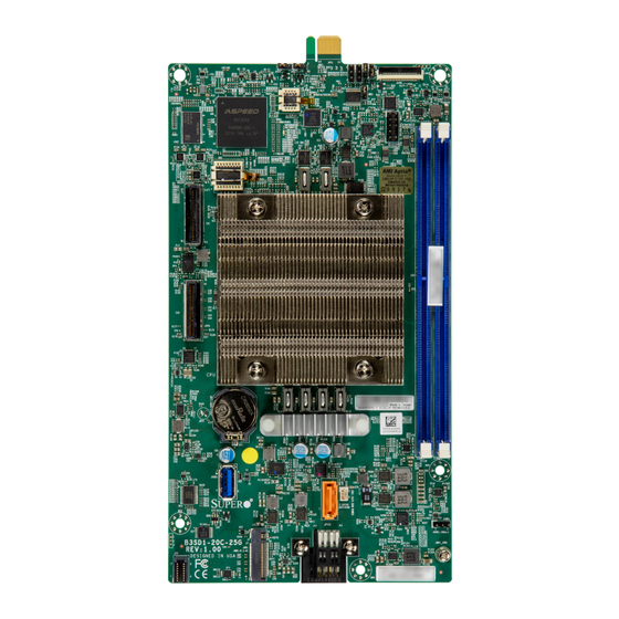
Introduction Congratulations on purchasing your computer motherboard from an industry leader. Supermicro motherboards are designed to provide you with the highest standards in quality and performance. In addition to the motherboard, several important parts that are included in the retail box are listed below. - Page 9 Chapter 1: Introduction Figure 1-1. B3SD1-20C-25G Motherboard Image Note: All graphics shown in this manual were based upon the latest PCB revision available at the time of publication of the manual. The motherboard you received may or may not look exactly the same as the graphics shown in this manual.
- Page 10 Super B3SD1-20C-25G User's Manual Figure 1-2. Motherboard Layout (not drawn to scale) JPT1 J24 JPV1 JKVM1 JWD1 LED1 JTPM1 BAR CODE JBT1 BIOS LICENSE JUSB1 JSD1 I-SATA0 JSMB1 JMD1 JMD1_SRW1 JPV2 MAC CODE Note: Components not documented are for internal testing only.
-
Page 11: Quick Reference
Chapter 1: Introduction Quick Reference LED1 JPV1 JKVM1 JPME2 JPT1 JPT1 J24 JPV1 JKVM1 JWD1 JWD1 JTPM1 LED1 JTPM1 BAR CODE JBT1 JBT1 BIOS LICENSE DIMMD1 DIMMC1 JUSB1 JUSB1 JSD1 JSD1 I-SATA0 I-SATA0 JSMB1 JMD1 JSMB1 JMD1_SRW1 JMD1_SRW1 JPV2 MAC CODE JMD1 JPV2 Notes:... -
Page 12: Quick Reference Table
Super B3SD1-20C-25G User's Manual Quick Reference Table Jumper Description Default Setting JBT1 Onboard CMOS Clear Open (Normal) JPME2 Manufacturing Mode Pins 1-2 (Normal) JPT1 Onboard TPM 2.0 Enable/Disable Pins 1-2 (Enable) JWD1 Watchdog Timer Pins 1-2 (Reset) Connector Description Onboard CMOS Battery... -
Page 13: Motherboard Features
Chapter 1: Introduction Motherboard Features Motherboard Features • Supports an Intel® Xeon® D-2796NT processor in a FCBGA 2579 socket with up to 20 cores and a TDP of up to 120 W Memory • Supports up to 256 GB of DDR4 ECC LRDIMM memory with speeds of up to 2933 MHz in two DIMM slots DIMM Size •... - Page 14 Note 2: For IPMI configuration instructions, refer to the Embedded IPMI Configuration User's Guide available at http://www.supermicro.com/support/manuals/. Note 3: If you purchase a Supermicro Out of Band (OOB) software license key (Supermicro P/N: SFT-OOB-LIC), DO NOT change the IPMI MAC address. Once the Mac address has been changed, the OOB license key will be invalid.
- Page 15 Chapter 1: Introduction Figure 1-3. System Block Diagram B3SD1-20C-25G DDR4 up to 2933 HDD backplane AOM-BPNIO-MSN2 PE0[15:0] PCIe 4.0 x4 PCIe 4.0 x4 PE1[15:12] PCIe 4.0 x4 M.2 (M-Key) PE1[3:0] 25G PHY GF Back Plane SATA3.0 Flexible I/O AOM-BPNIO-GFR Quad0...
-
Page 16: Processor Overview
Super B3SD1-20C-25G User's Manual 1.2 Processor Overview Built upon the functionality and capability of the Xeon D-2796NT processor, the B3SD1-20C- 25G motherboard provides optimized system performance, efficient power management, and features based on cutting edge technology to address today's needs in advanced computing, engineering simulations, and automation. -
Page 17: Environmental Temperature Control
Windows operating systems. For detailed information regarding OS support, refer to the Supermicro website. 1.6 Power Supply As with all computer products, a stable power source is necessary for proper and reliable operation. -
Page 18: Chapter 2 Installation
Super B3SD1-20C-25G User's Manual Chapter 2 Installation 2.1 Static-Sensitive Devices Electrostatic Discharge (ESD) can damage electronic com ponents. To avoid damaging your system board, it is important to handle it very carefully. The following measures are generally sufficient to protect your equipment from ESD. -
Page 19: Motherboard Installation
Chapter 2: Installation 2.2 Motherboard Installation All motherboards have standard mounting holes to fit different types of chassis. Make sure that the locations of all the mounting holes for both the motherboard and the chassis match. Although a chassis may have both plastic and metal mounting fasteners, metal ones are highly recommended because they ground the motherboard to the chassis. -
Page 20: Installing The Motherboard
Super B3SD1-20C-25G User's Manual Installing the Motherboard 1. Locate the mounting holes on the motherboard and the mounting tray. See the previous page for the location. 2. Install the standoffs on the mounting tray. Align the mounting holes on the motherboard against the mounting holes on the tray. -
Page 21: Assembling A Dual Node Microblade
Chapter 2: Installation Assembling a Dual Node MicroBlade Two MicroBlade nodes can be assembled to create a dual node configuration in one MicroBlade sled. AOM-BPNIO-GFR 1. Install a MicroBlade in the center of the MicroBlade sled and fasten all screws of this motherboard. JPV2 Note: This MicroBlade is Node 2. -
Page 22: Installing The Motherboard Into The Superblade Chassis
Super B3SD1-20C-25G User's Manual Installing the Motherboard into the Superblade Chassis 1. When the motherboard is securely installed on the mounting tray, push the tray into the Superblade chassis shown below. 2. Once the mounting tray is pushed into the chassis, the connectors on the motherboard's edge will make contact with the chassis' backplane, which provides the connections to the chassis power, network, and other I/O devices. -
Page 23: Memory Support And Installation
Important: Exercise extreme care when installing or removing DIMM modules to pre- vent any possible damage. Memory Support The B3SD1-20C-25G motherboard supports up to 256 GB of DDR4 ECC LRDIMM memory with speeds of up to 2933 MHz in two DIMM slots. 1 CPU, 4 DIMM Slots... -
Page 24: General Guidelines For Optimizing Memory Performance
Super B3SD1-20C-25G User's Manual General Guidelines for Optimizing Memory Performance • It is recommended to use DDR4 ECC LRDIMM memory of the same type, size and speed. • Mixed DIMM speeds can be installed. However, all DIMMs will run at the speed of the slowest DIMM. -
Page 25: Dimm Installation
Chapter 2: Installation DIMM Installation JPT1 J24 JPV1 JKVM1 1. For the system to work properly, use JWD1 LED1 JTPM1 memory modules of the same type and speed. Refer to the table in Chapter 2.3 the memory population sequence. 2. Align the DIMM module key with the BAR CODE receptive point on the single-latch DIMM JBT1... -
Page 26: Connectors & Headers
Super B3SD1-20C-25G User's Manual 2.4 Connectors & Headers Power Connections Gold Finger to JPV2 of Node 1 or Backplane through AOM-BPNIO-GFR for Power Delivery JPV1 is a gold finger to connect to JPV2 of Node 1 or the backplane through AOM-BPNIO- GFR for power delivery to the motherboard. - Page 27 Chapter 2: Installation Power Connector for HDD Backplane Located at J25 is a power connector for the HDD backplane. When the system has only one motherboard, connect J25 of Node 1 to the HDD backplane. When the system has two motherboards, connect J25 of Node 2 to the HDD backplane.
- Page 28 Super B3SD1-20C-25G User's Manual Headers MCIO Connectors CN1 and CN2 are MCIO connectors. Use CN1 to provide Ethernet and CMM management to the system. Use CN2 to connect to the HDD backplane. VGA/USB Module Connector Use JKVM1 to connect to a VGA/USB module.
- Page 29 Chapter 2: Installation SATA DOM Port This motherboard has one SATA DOM port at I-SATA1. I-SATA1 can be used with Supermicro SuperDOMs that are yellow SATA DOM connectors with power pins built in, and do not require external power cables. Supermicro SuperDOMs are backwards compatible with regular SATA HDDs or SATA DOMs that need external power cables.
- Page 30 Super B3SD1-20C-25G User's Manual System Management Bus Header A System Management Bus (SMBus) header for additional slave devices is located at JSMB1. Refer to the table below for pin definitions. SMBus Header Pin Definitions Pin# Definition Data Ground Clock Trusted Platform Module (TPM) Header A Trusted Platform Module (TPM)/Port 80 header is located at JTPM1 to provide TPM support and Port 80 connection.
- Page 31 Chapter 2: Installation Internal USB 3.0 Type-A Connector for Debugging There is one internal USB 3.0 port (JUSB1) on the motherboard. Use this port for USB debug access to the motherboard. Internal USB 3.0 Pin Definitions Pin# Definition Pin# Definition VBUS VBUS Stda_SSRX-...
-
Page 32: Jumper Settings
Super B3SD1-20C-25G User's Manual 2.5 Jumper Settings How Jumpers Work To modify the operation of the motherboard, jumpers can be used to choose between optional settings. Jumpers create shorts between two pins to change the function of the connector. Pin 1 is identified with a square solder pad on the printed circuit board. See the diagram below for an example of jumping pins 1 and 2. - Page 33 Chapter 2: Installation CMOS Clear JBT1 is used to clear CMOS, which will also clear any passwords. Instead of pins, this jumper consists of contact pads to prevent accidentally clearing the contents of CMOS. To Clear CMOS 1. First power down the system and unplug the power cord(s). 2.
- Page 34 Super B3SD1-20C-25G User's Manual Manufacturing Mode Close pins 2-3 of JPME2 to bypass SPI flash security and force the system to operate in manufacturing mode, which will allow you to flash the system firmware from a host server for system setting modifications. Refer to the table below for jumper setting.
- Page 35 Chapter 2: Installation Watchdog JWD1 controls the Watchdog function. Watchdog is a monitor that can reboot the system when a software application hangs. Jumping pins 1-2 will cause Watchdog to reset the system if an application hangs. Jumping pins 2-3 will generate a non-maskable interrupt signal for the application that hangs.
-
Page 36: Led Indicators
Super B3SD1-20C-25G User's Manual 2.6 LED Indicators BMC Heartbeat LED LED1 is the BMC Heartbeat LED. When the LED is blinking green, the BMC is working. Refer to the table below for the LED status. BMC Heartbeat LED LED Color... -
Page 37: Chapter 3 Troubleshooting
Chapter 3: Troubleshooting Chapter 3 Troubleshooting 3.1 Troubleshooting Procedures Use the following procedures to troubleshoot your system. If you have followed all of the procedures below and still need assistance, refer to the ‘Technical Support Procedures’ and/ or ‘Returning Merchandise for Service’ section(s) in this chapter. Always disconnect the AC power cord before adding, changing or installing any non hot-swap hardware components. -
Page 38: No Video
Super B3SD1-20C-25G User's Manual No Video 1. If the power is on, but you have no video, remove all add-on cards and cables. 2. Use the speaker to determine if any beep codes are present. Refer to Appendix A for details on beep codes. -
Page 39: Losing The System's Setup Configuration
Chapter 3: Troubleshooting 4. Check for bad DIMM modules or slots by swapping a single module among all memory slots and check the results. Losing the System's Setup Configuration 1. Make sure that you are using a high-quality power supply. A poor-quality power supply may cause the system to lose the CMOS setup information. - Page 40 Super B3SD1-20C-25G User's Manual B. If the system becomes unstable before or during OS installation, check the following: 1. Source of installation: Make sure that the devices used for installation are working properly, including boot devices such as a USB flash or media drive.
-
Page 41: Technical Support Procedures
Before contacting Technical Support, take the following steps. Also, note that as a motherboard manufacturer, Supermicro also sells motherboards through its channels, so it is best to first check with your distributor or reseller for troubleshooting services. They should know of any possible problems with the specific system configuration that was sold to you. -
Page 42: Frequently Asked Questions
3.3 Frequently Asked Questions Question: What type of memory does my motherboard support? Answer: The B3SD1-20C-25G supports up to 256 GB of DDR4 ECC LRDIMM memory with speeds of up to 2933 MHz in two DIMM slots. Question: How do I update my BIOS? Answer: It is recommended that you do not upgrade your BIOS if you are not experiencing any problems with your system. -
Page 43: Battery Removal And Installation
Chapter 3: Troubleshooting 3.4 Battery Removal and Installation Battery Removal To remove the onboard battery, follow the steps below: 1. Power off your system and unplug your power cable. 2. Locate the onboard battery as shown below. 3. Using a tool such as a pen or a small screwdriver, push the battery lock outwards to unlock it. -
Page 44: Returning Merchandise For Service
Super B3SD1-20C-25G User's Manual 3.5 Returning Merchandise for Service A receipt or copy of your invoice marked with the date of purchase is required before any warranty service will be rendered. You can obtain service by calling your vendor for a Returned Merchandise Authorization (RMA) number. -
Page 45: Chapter 4 Uefi Bios
Chapter 4: UEFI BIOS Chapter 4 UEFI BIOS 4.1 Introduction This chapter describes the AMIBIOS™ Setup utility for the motherboard. The BIOS is stored on a chip and can be easily upgraded using a flash program. Note: Due to periodic changes to the BIOS, some settings may have been added or deleted and might not yet be recorded in this manual. -
Page 46: Main Setup
Super B3SD1-20C-25G User's Manual 4.2 Main Setup When you first enter the AMI BIOS setup utility, you enter the Main setup screen. You can always return to the Main setup screen by selecting the Main tab on the top of the screen. -
Page 47: Advanced Setup Configurations
Chapter 4: UEFI BIOS 4.3 Advanced Setup Configurations Use the arrow keys to select the Advanced submenu and press <Enter> to access the submenu items. Warning: Take caution when changing the Advanced settings. An incorrect value, an improper DRAM frequency, or a wrong BIOS timing setting may cause the system to malfunction. When this occurs, revert the setting to the manufacture default settings. - Page 48 Super B3SD1-20C-25G User's Manual Wait For "F1" If Error Use this feature to force the system to wait until the <F1> key is pressed if an error occurs. The options are Disabled and Enabled. Re-try Boot If this feature is enabled, the BIOS automatically reboots the system from a specified boot device after its initial boot failure.
- Page 49 Chapter 4: UEFI BIOS • Processor Max Ratio • Processor Min Ratio • Microcode Revision • L1 Cache RAM (Per Core) • L2 Cache RAM (Per Core) • L3 Cache RAM (Per Package) • Processor 0 Version CPU1 Core Disable Bitmap CPU1 Core Disable Bitmap Available Bitmap CPU Core Count...
- Page 50 Super B3SD1-20C-25G User's Manual DCU IP Prefetcher (Available when supported by the CPU) Select Enable for Data Cache Unit (DCU) IP Prefetcher support, which prefetches IP addresses to improve network connectivity and system performance. The options are Enable and Disable.
- Page 51 Chapter 4: UEFI BIOS Total Memory Encryption Multi-Tenant (TME-MT) (Available when "Total Memory Encryption" is set to "Enabled") Use this feature to enable or disable Total Memory Encryption Multi-Tenant (TME-MT). The options are Disabled and Enabled. When "Limit CPU PA to 46 Bits" is set to Enable, this feature will be disabled.
- Page 52 Super B3SD1-20C-25G User's Manual CPU P State Control SpeedStep (Pstates) Intel SpeedStep Technology allows the system to automatically adjust processor voltage and core frequency to reduce power consumption and heat dissipation. The options are Disable and Enable. AVX P1 Use this feature to select the AVX-P1 level. The options are Nominal, Level 1, and Level...
- Page 53 Chapter 4: UEFI BIOS CPU C State Control Enable Monitor MWAIT Select Enable to enable the Monitor/Mwait instructions. The Monitor instructions monitors a region of memory for writes, and MWait instructions instruct the CPU to stop until the monitored region begins to write. The options are Disable and Enable. CPU C6 Report Select Enable to allow the BIOS to report the CPU C6 State (ACPI C3) to the operating system.
- Page 54 Super B3SD1-20C-25G User's Manual Chipset Configuration Warning: Setting the wrong values in the following features may cause the system to malfunc- tion. North Bridge Uncore Configuration Uncore Configuration • Number of CPU • Number of IIO • Current UPI Link Speed •...
- Page 55 Chapter 4: UEFI BIOS Memory Configuration Enforce POR Select Plan of Record (POR) to enforce POR restrictions on DDR4 frequency and volt- age programming. The options are POR and Disable. PPR Type Use this feature to select the Post Package Repair (PPR) type. The options are PPR Disabled, Hard PPR, and Soft PPR.
- Page 56 Super B3SD1-20C-25G User's Manual Leaky Bucket Low Bit Use this feature to set the Low Bit value for the Leaky Bucket algorithm, which is used to check the data transmissions between the CPU socket and the memory controller. The default setting is 13.
- Page 57 Chapter 4: UEFI BIOS CPU Slot6 PCIe 4.0 x16 Link Speed Use this feature to override the link speed. The options are Auto, Gen 1 (2.5 GT/s), Gen 2 (5 GT/s), Gen 3 (8 GT/s), and Gen 4 (16 GT/s). Override Max Link Width Use this feature to override the max link width set by the PCIe bifurcation setting.
- Page 58 Super B3SD1-20C-25G User's Manual Embar2 Size Use this feature to set a value for the prefetchable Embar2 size on the secondary side of NTB. The value can be a number in the range of 12 to 51 representing BAR sizes from 4 KB to 128 PB. The default setting is 22.
- Page 59 Chapter 4: UEFI BIOS Intel VMD Technology Intel VMD for Volume Management Device on CPU1 VMD Config for PCH ports Enable/Disable VMD Use this feature to enable or disable the volume management device for this stack. The options are Disable and Enable. JMD1:M.2-H PCIe 3.0 x4/S-SATA 3.0 VMD (Available when "VMD Config for PCH ports"...
- Page 60 Super B3SD1-20C-25G User's Manual JSLIM1 PCIe 4.0 x8 VMD Port 0 / JSLIM1 PCIe 4.0 x8 VMD Port 1 / JSLIM1 PCIe 4.0 x8 VMD Port 2 / JSLIM2 PCIe 4.0 x8 VMD Port 0 / JSLIM2 PCIe 4.0 x8 VMD Port 1 (Available when "VMD Config for PCH ports" is set to "Enable")
- Page 61 Chapter 4: UEFI BIOS PCIe PLL SSC Use this feature to enable or disable PCIe PLL SSC. The options are Disabled and Enabled. Server ME Information The following General ME Configuration is displayed: • General ME Configuration • Oper. Firmware Version •...
- Page 62 Super B3SD1-20C-25G User's Manual Trusted Computing The following Trusted Platform Module (TPM) information will display if a TPM 2.0 module is detected: • Firmware Version • Vendor Name Security Device Support If this feature and the TPM jumper on the motherboard are both set to Enabled, onboard security devices will be enabled for Trusted Platform Module (TPM) support to enhance data integrity and network security.
- Page 63 Chapter 4: UEFI BIOS PH Randomization Use this feature to disable or enable Platform Hierarchy (PH) Randomization. The options are Disabled and Enabled. ACPI Settings WHEA Support Select Enabled to support the Windows Hardware Error Architecture (WHEA) platform and provide a common infrastructure for the system to handle hardware errors within the Windows OS environment to reduce system crashes and to enhance system recovery and health monitoring.
- Page 64 Super B3SD1-20C-25G User's Manual Device Settings This feature displays the status of the specified serial port. Change Settings This feature specifies the base I/O port address and the Interrupt Request address of the specified serial port. Select Auto to allow the BIOS to automatically assign the base I/O and IRQ address.
- Page 65 Chapter 4: UEFI BIOS IPv6 HTTP Support (Available when Network Stack is set to "Enabled") Use this feature to enable IPv6 HTTP boot support. The options are Disabled and Enabled. PXE boot wait time (Available when Network Stack is set to "Enabled") Enter a value for the wait time (in seconds) to press the <ESC>...
- Page 66 Super B3SD1-20C-25G User's Manual MAC: XXXXXXXXXXXX-IPv6 Network Configuration MAC: XXXXXXXXXXXX-IPv6 Network Configuration Enter Configuration Menu Information for the following is displayed: • Interface Name • Interface Type • MAC address • Host addresses • Route Table • Gateway addresses •...
- Page 67 Chapter 4: UEFI BIOS Commit Changes and Exit Select this feature to save the changes you've made and return to the upper configu- ration page. Discard Changes and Exit Select this feature to discard all the changes and return to the upper configuration page. Save Changes and Exit Select this feature to save the changes you've made and return to the upper configura- tion page.
- Page 68 Super B3SD1-20C-25G User's Manual MMIO High Granularity Size Use this feature to select the high memory size according to memory-address mapping for the IO hub. The options are 1G, 4G, 16G, 64G, 256G, and 1024G. Maximum Read Request Use this item to select the Maximum Read Request size of the PCIe device, or select Auto to allow the System BIOS to determine the value.
- Page 69 The options are Enabled and Disabled (WARNING: Security Risk!!). Warning: Disabling this option is a violation of RFC 6125 and may expose you to Man-in-the-Middle Attacks. Supermicro is not responsible for any and all security risks incurred by you disabling this option. Priority of HTTP Boot Instance of Priority 1 Use this feature to rank the targeted port.
- Page 70 Use this feature to enter the second Supermicro KMS server IPv4 address in dotted-decimal notation. Supermicro KMS TCP Port number Use this feature to enter the Supermicro KMS TCP port number. The valid range is 100 – 9999. The default setting is 5696. KMS Time Out Use this feature to enter the KMS server connecting time-out (in seconds).
- Page 71 Super-Guardians Configuration Super Guardians is a unified security solution to facilitate KMS, TPM, or USB-based authentication controls for Supermicro X13 motherboards. Use this submenu to configure the authentication policy, method, and KMS server settings. Super-Guardians Protection Policy Use this feature to enable the Super-Guardians Protection Policy. The options are Storage, System, and "System and Storage."...
- Page 72 Note 1: Be sure that the KMS server is ready before configuring this feature. Note 2: Use the professional KMS server solutions (e.g., Thales Server) or the Supermicro PyKMIP Software Package to establish the KMS server. When this feature has previously been set to Enabled, the options are Enabled, Reset, and Key Rotation.
- Page 73 Chapter 4: UEFI BIOS Save Authentication-Key Use this feature to toggle whether the BIOS should automatically save an Authentication-Key with the name TPMAuth.bin to a USB flash drive. The options are Disabled and Enabled. After an Authentication Key is saved, this option will be reset to Disabled. Changes take effect after you save settings and reboot the system.
- Page 74 Super B3SD1-20C-25G User's Manual NIC Configuration Link Speed Use this feature to specify the port speed for this port. The default setting is Auto Ne- gotiated. Wake On Lan Use this feature to enable or disable Wake On Lan support. Wake On Lan allows the system to wake up when an onboard LAN device receives an incoming signal.
- Page 75 Chapter 4: UEFI BIOS • Device Name • Chip Type • PCI Device Id • PCI Address • Link Status • MAC Address • Virtual MAC Address TLS Authenticate Configuration This submenu allows you to configure Transport Layer Security (TLS) settings. Server CA Configuration Enroll Cert Enroll Certification Using File...
- Page 76 Super B3SD1-20C-25G User's Manual Client Certification Configuration Enroll Certification Enroll Certification Using File Use this feature to enroll certification from a file. Certification GUID Use this feature to input the certification Global Unique Identifier (GUID). Commit Changes and Exit Use this feature to save all changes and exit TLS settings.
- Page 77 Chapter 4: UEFI BIOS Discard & Exit Use this feature to save all changes and exit raw RAM disk settings. Create from file Use this feature to create a RAM disk from a specified file. Created RAM disk list: Use this feature to select a RAM disk. Remove selected RAM disks(s).
-
Page 78: Event Logs
Super B3SD1-20C-25G User's Manual 4.4 Event Logs Use this feature to configure Event Log settings. Change SMBIOS Event Log Settings Enabling/Disabling Options SMBIOS Event Log Change this feature to enable or disable all features of the SMBIOS Event Logging during system boot. - Page 79 Chapter 4: UEFI BIOS SMBIOS Event Log Standard Settings Log System Boot Event This option toggles the System Boot Event logging to enabled or disabled. The options are Enabled and Disabled. MECI The Multiple Event Count Increment (MECI) counter counts the number of occurrences that a duplicate event must happen before the MECI counter is incremented.
-
Page 80: Bmc
Super B3SD1-20C-25G User's Manual 4.5 BMC Use this feature to configure Baseboard Management Console (BMC) settings. BMC Firmware Revision This feature indicates the BMC firmware revision used in your system. BMC STATUS This feature indicates the status of the BMC firmware installed in your system. - Page 81 Chapter 4: UEFI BIOS When SEL is Full (Available when SEL Components is set to "Enabled") This feature allows you to decide what the BIOS should do when the system event log is full. Select Erase Immediately to erase all events in the log when the system event log is full.
- Page 82 Super B3SD1-20C-25G User's Manual Station MAC Address (Available when "Configuration Address Source" is set to "Static") This feature displays the Station MAC address for this computer. Mac addresses are six two-digit hexadecimal numbers. Gateway IP Address (Available when "Configuration Address Source" is set to "Static")
- Page 83 Chapter 4: UEFI BIOS IPv6 Router 1 IP Address (Available when "Configuration Address Source" is set to "Static Configuration") Use this feature to set the IPv6 Router1 IP address from BMC in Static Configuration.
-
Page 84: Security
Super B3SD1-20C-25G User's Manual 4.6 Security This menu allows you to configure the following security settings for the system. Administrator Password This feature indicates if an administrator password has been set. Press <Enter> to create a new or change an existing administrator password. The length of the password can be between three to 20 characters long. - Page 85 The options are Disabled and Enabled. Supermicro Security Erase Configuration Note: This submenu becomes configurable when a storage device has been plugged into the motherboard. The features displayed in this section will change depending on what storage devices are detected.
- Page 86 Super B3SD1-20C-25G User's Manual Secure Boot Note: For detailed instructions on how to configure Security Boot settings, refer to the Security Boot Configuration User's Guide posted on the web page under the link: http:// www.supermicro.com/support/manuals/. This section displays the contents of the following secure boot features: •...
- Page 87 Chapter 4: UEFI BIOS Key Management (Available when "Secure Boot Mode" is set to "Custom") The following information is displayed. • Vendor Keys Provision Factory Defaults Select Enabled to install provision factory default settings after the platform reset while the system is in the Setup Mode.
- Page 88 Super B3SD1-20C-25G User's Manual of the authorized signatures. Select Update to update your "Platform Key." The default option is Update. Key Exchange Key (KEK) Use this feature to enter and configure a set of values to be used as Key-Exchange-Keys for the system.
-
Page 89: Boot
Chapter 4: UEFI BIOS 4.7 Boot Use this feature to configure Boot Settings: Fixed Boot Order Priorities This feature prioritizes the order of a bootable device from which the system will boot. Press <Enter> on each item sequentially to select devices. The displayed options change depending on the setting for "Boot Mode Select."... - Page 90 Super B3SD1-20C-25G User's Manual Create Use this feature to create the new boot option in the boot priority list after the name and file path for the boot option are set. Delete Boot Option This feature allows you to select a boot device to delete from the boot priority list.
-
Page 91: Save & Exit
Chapter 4: UEFI BIOS 4.8 Save & Exit Use this feature to save the configurations or leave the BIOS Setup utility. Save Options Discard Changes and Exit Select this feature to leave the BIOS Setup utility without making any permanent changes to the system configuration, and reboot the computer. - Page 92 Super B3SD1-20C-25G User's Manual Default Options Load Optimized Defaults Select this feature and press <Enter> to load the optimized defaults. These are factory settings designed for maximum system stability, but not for maximum performance. Save As User Defaults Select this feature and press <Enter> to save as the user defaults. This enables you to save any changes to the BIOS setup for future use.
-
Page 93: Appendix A Bios Codes
Appendix A: BIOS Codes Appendix A BIOS Codes A.1 BIOS Error POST (Beep) Codes During the Power-On Self-Test (POST) routines, which are performed each time the system is powered on, errors may occur. Non-fatal errors are those which, in most cases, allow the system to continue the boot-up process. -
Page 94: Additional Bios Post Codes
Super B3SD1-20C-25G User's Manual A.2 Additional BIOS POST Codes The AMI BIOS supplies additional checkpoint codes, which are documented online at http:// www.supermicro.com/support/manuals/ ("AMI BIOS POST Codes User's Guide"). For information on AMI updates, refer to http://www.ami.com/products/. -
Page 95: Appendix B Software
1. Create a method to access the Microsoft Windows installation ISO file. That can be a USB flash or media drive. 2. Retrieve the proper RST/RSTe driver. Go to the Supermicro web page for your motherboard and click on "Download the Latest Drivers and Utilities," select the proper driver, and copy it to a USB flash drive. - Page 96 Super B3SD1-20C-25G User's Manual 4. During Windows Setup, continue to the dialog where you select the drives on which to install Windows. If the disk you want to use is not listed, click on “Load driver” link at the bottom left corner.
- Page 97 Appendix B: Software B.2 Driver Installation The Supermicro website that contains drivers and utilities for your system is at https://www. supermicro.com/wdl/driver/. Some of these must be installed, such as the chipset driver. After accessing the website, go into the CDR_Images (in the parent directory of the above link) and locate the ISO file for your motherboard.
- Page 98 B.3 SuperDoctor ® The Supermicro SuperDoctor 5 is a program that functions in a command-line or web-based interface for Windows and Linux operating systems. The program monitors such system health information as CPU temperature, system voltages, system power consumption, fan speed, and provides alerts via email or Simple Network Management Protocol (SNMP).
- Page 99 There are several BIOS settings that are related to IPMI. Supermicro ships standard products with a unique password for the BMC ADMIN user. This password can be found on a label on the motherboard. For general documentation and information on IPMI, visit our website at http://www.supermicro.com/products/nfo/IPMI.cfm.
- Page 100 The following statements are industry standard warnings, provided to warn the user of situations which have the potential for bodily injury. Should you have questions or experience difficulty, contact Supermicro's Technical Support department for assistance. Only certified technicians should attempt to install or configure components.
- Page 101 Appendix C: Standardized Warning Statements Attention Danger d'explosion si la pile n'est pas remplacée correctement. Ne la remplacer que par une pile de type semblable ou équivalent, recommandée par le fabricant. Jeter les piles usagées conformément aux instructions du fabricant. ¡Advertencia! Existe peligro de explosión si la batería se reemplaza de manera incorrecta.
- Page 102 Super B3SD1-20C-25G User's Manual Product Disposal Warning! Ultimate disposal of this product should be handled according to all national laws and regulations. 製品の廃棄 この製品を廃棄処分する場合、 国の関係する全ての法律 ・ 条例に従い処理する必要があります。 警告 本产品的废弃处理应根据所有国家的法律和规章进行。 警告 本產品的廢棄處理應根據所有國家的法律和規章進行。 Warnung Die Entsorgung dieses Produkts sollte gemäß allen Bestimmungen und Gesetzen des Landes erfolgen.
Need help?
Do you have a question about the B3SD1-20C-25G and is the answer not in the manual?
Questions and answers