Table of Contents
Advertisement
Quick Links
BPN-SAS3-815TQ B
S
UPER
R
SAS815TQ
REV 1.00
+12V
GND
GND
+5V
JP10
J8
#3
JP29:9071 RST
JTAG
UPGRADE
JP29
#2
JP47
J7
+5V
+12V
J9
USeR'S GUIDe
1.0
AckPlANe
JP18:BUZZER RESET
JP18
D3
+5V
+12V
#1
J6
J10
JP40
JP42
JP51
JP33
JP34
MH2
M46
M9 M15
SIDEBAND
JP50
#0
J5
JP26
2
I C
JP44
ACT IN
ACT2 ACT3
ACT0
ACT1
Advertisement
Table of Contents

Related Manuals for Supermicro BPN-SAS3-815TQ


Summary of Contents for Supermicro BPN-SAS3-815TQ
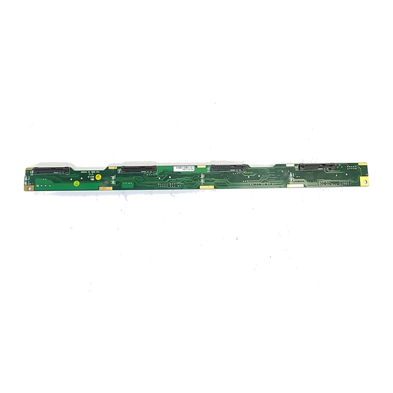
- Page 1 BPN-SAS3-815TQ B AckPlANe JP29:9071 RST JP18:BUZZER RESET JP40 JP42 JP51 UPER SAS815TQ JTAG UPGRADE JP29 JP18 JP33 REV 1.00 JP34 M9 M15 SIDEBAND JP50 +12V JP47 JP10 +12V +12V JP26 JP44 ACT IN ACT2 ACT3 ACT0 ACT1 USeR'S GUIDe...
- Page 2 Please Note: For the most up-to-date version of this manual, please see our web site at www.supermicro.com. Super Micro Computer, Inc. ("Supermicro") reserves the right to make changes to the product described in this manual at any time and without notice. This product, including software, if any, and documentation may not, in whole or in part, be copied, photocopied, reproduced, translated or reduced to any medium or machine without prior written consent.
-
Page 3: Table Of Contents
Contents Contents Contacting Supermicro ..................iv Returning Merchandise for Service..............v Chapter 1 Guidelines ESD Safety Guidelines ................... 1-1 General Safety Guidelines ................1-1 Version Information ..................1-2 Chapter 2 Connectors, Jumpers and LEDs Rear Connector Locations ................2-1 2-2 Rear Connector Definitions ................2-2 2-3 Rear Jumpers and Pin Definitions .............. -
Page 4: Contacting Supermicro
BPN-SAS3-815TQ Backplane Manual Contacting Supermicro Headquarters Address: Super Micro Computer, Inc. 980 Rock Ave. San Jose, CA 95131 U.S.A. Tel: +1 (408) 503-8000 Fax: +1 (408) 503-8008 Email: marketing@supermicro.com (General Information) support@supermicro.com (Technical Support) Web Site: www.supermicro.com Europe Address: Super Micro Computer B.V. -
Page 5: Returning Merchandise For Service
For faster service, RMA authorizations may be requested online (http://www. supermicro.com/support/rma/). Whenever possible, repack the backplane in the original Supermicro box, using the original packaging materials. If these are no longer available, be sure to pack the backplane in an anti-static bag and inside the box. Make sure that there is enough packaging material surrounding the backplane so that it does not become damaged during shipping. - Page 6 BPN-SAS3-815TQ Backplane Manual Notes...
-
Page 7: Chapter 1 Guidelines
Chapter 1 Guidelines This chapter offers guidelines for personal and equipment safety, and notes about the BPN-SAS3-815TQ version documented in this manual. ESD Safety Guidelines Electrostatic Discharge (ESD) can damage electronic com ponents. To prevent damage to your system, it is important to handle it very carefully. The following measures are generally sufficient to protect your equipment from ESD. -
Page 8: Version Information
This manual reflects BPN-SAS3-815TQ, Revision 1.00, the most current release available at the time of publication. Refer to the Supermicro Web site at www.supermicro.com for the latest updates, compatible parts and supported... -
Page 9: Chapter 2 Connectors, Jumpers And Leds
Chapter 2 Connectors, Jumpers and LEDs Chapter 2 Connectors, Jumpers and LEDs This manual covers BPN-SAS3-815TQ enabling SAS3 drives with 12Gbps speeds. Rear Connector Locations The following connectors are on the side of the backplane that faces the rear of the chassis. -
Page 10: Rear Connector Definitions
BPN-SAS3-815TQ Backplane Manual 2-2 Rear Connector Definitions 1. Backplane Main Power Connectors Main Power (JP10) The 4-pin connectors, designated JP10 Pin# Definition provide power to the backplane. +12V 2 and 3 Ground 2. Peripheral Drive 4-Pin Connectors Peripheral Drive Power (J9 and J10) - Page 11 Chapter 2 Connectors, Jumpers and LEDs 7. I C Connectors C Connector (JP44) The I C Connectors, designated JP44, are Pin# Definition used to monitor HDD activity and status. Data Ground Clock No Connection 8. Activity LED Header SAS Activity LED Header (JP26) The Activity LED header, designated JP26, Pin # Definition...
-
Page 12: Rear Jumpers And Pin Definitions
BPN-SAS3-815TQ Backplane Manual 2-3 Rear Jumpers and Pin Definitions JP29 JP18 SAS815TQ JTAG UPGRADE JP29:9071 RST JP18:BUZZER RESET JP40 JP42 JP51 UPER JP29 JP18 JP33 REV 1.00 JP34 M9 M15 JP50 SIDEBAND +12V JP47 JP10 +12V +12V JP26 JP44 ACT IN ACT2 ACT3 ACT0... -
Page 13: C And Sgpio Modes And Jumper Settings
Chapter 2 Connectors, Jumpers and LEDs C and SGPIO Modes and Jumper Settings This backplane can utilize I C or SGPIO. SGPIO is the default mode and can be used without making changes to your jumpers. Use the following settings for I mode. -
Page 14: Rear Led Indicators
BPN-SAS3-815TQ Backplane Manual Rear LED Indicators SAS815TQ JTAG UPGRADE JP29:9071 RST JP18:BUZZER RESET JP40 JP42 JP51 UPER JP29 JP18 JP33 REV 1.00 JP34 M9 M15 JP50 SIDEBAND +12V JP47 JP10 +12V +12V JP26 JP44 ACT IN ACT0 ACT1 ACT2 ACT3... -
Page 15: Front Connectors And Led Indicators
Chapter 2 Connectors, Jumpers and LEDs Front Connectors and LED Indicators The front of the backplane has four sockets to connect disk drives, along with LEDs indicators. M 9 M 1 H 2 M 4 SAS #3 SAS #0 SAS #1 SAS #2 Figure 2-4. - Page 16 BPN-SAS3-815TQ Backplane Manual Disclaimer (cont.) The products sold by Supermicro are not intended for and will not be used in life support systems, medical equipment, nuclear facilities or systems, aircraft, aircraft devices, aircraft/emergency communication devices or other critical systems whose failure to perform be reasonably expected to result in significant injury or loss of life or catastrophic property damage. Accordingly, Supermicro...
Need help?
Do you have a question about the BPN-SAS3-815TQ and is the answer not in the manual?
Questions and answers