Table of Contents
Advertisement
Quick Links
Advertisement
Table of Contents

Related Manuals for Glow-worm EASICOM 25s


Summary of Contents for Glow-worm EASICOM 25s
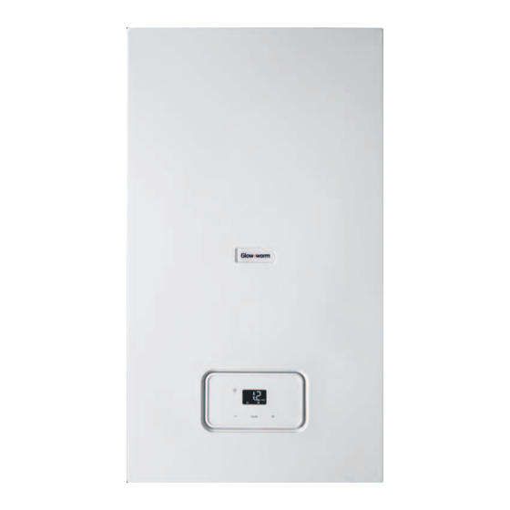
- Page 1 The energy you need Operating instruc- tions EASICOM GB, IE...
-
Page 2: Table Of Contents
Contents Contents Care and maintenance ....13 Maintenance ........ 13 Safety ..........3 Caring for the product ....13 Action-related warnings ....3 Checking the condensate drain Intended use ........3 pipework and tundish....13 General safety information..... 4 Decommissioning...... 13 Notes on the documentation .. -
Page 3: Safety
Safety 1 ral heating installations and for 1 Safety hot water generation. 1.1 Action-related warnings Intended use includes the fol- Classification of action-re- lowing: lated warnings – observance of the operating The action-related warnings instructions included for the are classified in accordance product and any other system with the severity of the pos- components... -
Page 4: General Safety Information
1 Safety ▶ Do not use any electrical 1.3 General safety switches, mains plugs, door- information bells, telephones or other 1.3.1 Installation by skilled communication systems in tradesmen only the building. The installation, inspection, ▶ If it is safe to do so, close the maintenance and repair of the emergency control valve or product, as well as the gas ratio... - Page 5 Safety 1 – The product itself flue gas may escape into the room air. – to the gas, air, water and electricity supplies ▶ In order to operate the – to the entire flue gas install- product, ensure that the con- ation densate siphon is always full.
-
Page 6: Notes On The Documentation
1 Safety lead to corrosion on the product 2 Notes on the and in the air/flue pipe. documentation ▶ Ensure that the supply of 2.1 Observing other applicable combustion air is always free documents of fluorine, chlorine, sulphur, ▶ You must observe all operating instruc- dust, etc. -
Page 7: Product Description
The serial number is located on the identi- at the manufacturer's site. fication plate (1) and in the short operating instructions (2) (→ Page 7). 3.2 Benchmark Glow-worm is a licensed member of the 3.4 Information on the Benchmark Scheme. identification plate Benchmark places responsibilities on both The identification plate is mounted on the manufacturers and installers. -
Page 8: Overview Of The Operator Control Elements
3 Product description 3.6 Description of the display Information Meaning on the identi- fication plate Type: Xx3(x) Approved flue gas connec- tions Maximum water pressure in heating mode Maximum water pressure in hot water handling mode V/Hz Electric connection Max. electrical power con- Operating in- Display showing sumption... -
Page 9: Description Of Button Functions
Operation 4 3.8 Operating levels Symbol Meaning The product has two operating levels: Heating mode – Permanently on: Heating – The operator level shows the most im- mode activated portant information and offers set-up – Flashing: Burner on in options which do not require any special heating mode prior knowledge. -
Page 10: Basic Display
4 Operation 4.2 Basic display 4.4 Filling the heating installation Caution. Risk of material damage due to heating water that is ex- tremely calciferous or corros- ive or contaminated by chem- icals. Unsuitable tap water damages the seals and diaphragms, blocks components in the The filling pressure in the heating installa- tion and the operating mode are shown in... -
Page 11: Selecting The Operating Mode
Operation 4 4.5 Selecting the operating mode Conditions: Temperature controlled by the control- ler, with heating mode activated Note ▶ Set the maximum heating flow temper- The unit is always activated with ature on the boiler (→ Page 11). the preselected operating mode. ▶... -
Page 12: Frost Protection
5 Troubleshooting ◁ The main power supply is not inter- Conditions: If you are away from home for several rupted. The product continues to be days, With controller supplied with power. ▶ Program the number of days you will be away in the controller to activate the 4.10 Frost protection frost protection devices. -
Page 13: Care And Maintenance
Care and maintenance 6 6 Care and maintenance 7 Decommissioning 6.1 Maintenance 7.1 Temporarily decommissioning the product An annual inspection of the product carried ▶ out by a competent person is a prerequis- Temporarily decommission the product ite for ensuring that the product is perman- only if there is no risk of frost. -
Page 14: Guarantee And Customer Service
9.2 Customer service For contact details for our customer ser- vice department, you can write to the ad- dress that is provided on the back page, or you can visit www.glow-worm.co.uk. Operating instructions EASICOM 0020238425_01... -
Page 15: Appendix
Appendix Appendix A Operator level – overview Setting level Values Unit Increment, select Factory set- tings Min. Max. Heating installation Pressure in the heating in- Current value stallation ℃ Heating flow temperature Current value Preset in the system B Troubleshooting Fault Cause Measure... - Page 16 Appendix Fault Cause Measure Product does not After three successive failed ignition Press the button. The product start up: attempts, the system switches to fault carries out a new ignition attempt. mode (fault code: F.28). If the ignition problem is not rec- –...
- Page 20 Publisher/manufacturer Glow-worm Nottingham Road ‒ Belper ‒ Derbyshire DE56 1JT Telephone 01773 824639 ‒ Technical helpline 0330 100 7679 After sales service 0330 100 3142 www.glow-worm.co.uk 0020238425_01 0020238425_01 ‒ 17.07.2019 supplier © These instructions, or parts thereof, are protected by copyright and may be reproduced or distributed only with the manufacturer's written consent.
Need help?
Do you have a question about the EASICOM 25s and is the answer not in the manual?
Questions and answers