
Related Manuals for Glow-worm ENERGY


Summary of Contents for Glow-worm ENERGY
- Page 1 Installation manual Air/flue systems ENERGY, ULTIMATE, EASICOM, ESSENTIAL, BETACOM, MICRACOM GB, IE...
- Page 2 Contents Contents Safety ..............3 Action-related warnings ......... 3 Intended use ............3 General safety information ........3 CE certification............5 Regulations (directives, laws, standards) ....5 Notes on the documentation ......6 Observing other applicable documents ....6 Storing documents..........6 Validity of the instructions ........
- Page 3 Safety 1 Safety General safety information 1.3.1 Risk caused by inadequate Action-related warnings qualifications Classification of action-related warnings The following work must only be carried out The action-related warnings are classified in by competent persons who are sufficiently accordance with the severity of the possible qualified to do so: danger using the following warning signs and –...
- Page 4 1 Safety – Downward gradient to the product: 3° ▶ To facilitate the installation, use only wa- ter, standard commercial soft soap or, if re- quired, the supplied lubricant. Note 3° corresponds to a downward Mortar residues, shavings, etc., in the flue gradient of approx.
- Page 5 Glow-worm article num- bers that are designed for the air/flue pipe is provided. If you do not use certified ele- ments for the Glow-worm air/flue pipe when installing the heat generators, this voids the CE conformity of the heat generator. We therefore strongly recommend that you in- stall Glow-worm air/flue systems.
- Page 6 2 Notes on the documentation Notes on the documentation Observing other applicable documents ▶ You must always observe the installation instructions for the installed heat generator. Storing documents ▶ Pass these instructions and all other applicable docu- ments on to the end user. Validity of the instructions These instructions apply only for the heat generators named in the other applicable documents, hereinafter referred to as...
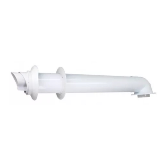
- Page 7 Certified air/flue systems and components 3 Certified air/flue systems and components System overview, 60/100 mm diameter Article number Air/flue systems, concentric 1), 3) Horizontal wall/roof duct, 0.7 m 0020219523 0010031041 1), 3) Horizontal telescopic wall/roof duct (only available in black) 0020219524 Direct, rear-side, telescopic flue system 0020219526...
- Page 8 3 Certified air/flue systems and components Article num- 0020219523 0020219524 0020219526 0020230604 0010035513 0010031041 –– –– 87° elbow for variable terminal set 0020219545 (VTK), black –– –– –– 87° elbow for variable terminal set 0020219550 (VTK), white 1 In accordance with the construction regulation, installation on the external wall in buildings higher than 18 m is permitted. The sleeve end of the extension must protrude at least 60 mm from the wall to comply with fire-protection requirements.
- Page 9 System conditions 4 System conditions Danger! Risk of poisoning due to escaping flue Route of the air/flue pipe in buildings gas. The air/flue system should be as short as possible and run Condensate that collects inside the flue in as straight as possible. certain areas can damage the flue pipework ▶...
- Page 10 5 Set-up 5.1.1.2 Determining the clearance to the external wall Note View shows article number 0010031041 Clearance Article number 0010035513 0020219523 0010031041 87 mm 140 mm The mounting template indicates the position for horizontal installation of the air/flue pipe when connecting it to the up- per side of the boiler.
- Page 11 Set-up 5 5.1.2.2 Scope of delivery, article number 5.1.2.4 Installing the wall duct 0010035513 Ø167 Drill a hole. – Diameter: 125 mm Clearance Article number Wall collar, 100 dia- 87° elbow 0010035513 0020219523 meter (2 pcs) Screws (8 x) 0010031041 Horizontal wall/roof duct Seal 87 mm...
- Page 12 5 Set-up 5.1.2.5 Installing the roof duct Set the telescopic wall duct to the correct length. – Note that the TOP symbol must point upwards on ▶ Insert the air/flue pipe (1) without the external collar into both ends. the dormer. –...
- Page 13 Set-up 5 5.1.4 Connecting the product 5.1.5.2 Determining the pipe length and the location of the wall duct Y + 24 - 28 120 - 500 Install the product (6) – see the installation instructions for the product. Install the 87° elbow (1) on the product using the four screws and the seal.
- Page 14 5 Set-up – Secure the air pipes to each other by screwing the over- If you install the wall collar, add 12 mm to the total lapping air pipes together using the supplied self-tap- pipe length. ping screws (1) on the underside. –...
- Page 15 Set-up 5 Black terminal set – article number 5.1.8 0020219538 5.1.8.1 Scope of delivery Note Not valid for article number 0010035513 Release the catch between the opening piece and the end pipe. Wall collar End pipe Terminal piece 5.1.8.2 Installing the black terminal (change of colour) Note Pull the end pipe from the opening piece.
- Page 16 5 Set-up 5.1.9.1 Scope of delivery Wall collar Deflector Slide the new opening piece onto the flue pipe until you Opening piece hear the opening piece click into place. – Deflector set, DN 60, PP, black (article number 0020219535) – Deflector set, DN 60, PP, white (article number 0020219536) 5.1.9.2 Installing the deflector set...
- Page 17 Set-up 5 ▶ Slide the deflector onto the opening piece until you hear the deflector click into place. 5.1.9.3 Adjusting the deflector ▶ Set the terminal to the required position. – The flue gas stream is directed upwards at an angle of approx.
- Page 18 Note Not valid for article number 0010035513 Pipe length A Maximum pipe length A + B Pipe length B ENERGY 10.0 ULTIMATE ESSENTIAL EASICOM BETACOM MICRACOM 1) The inclusion of additional elbows in the flue system reduces the pipe length as follows: –...
- Page 19 Set-up 5 5.1.10.2 Opening in the air/flue pipe D, E Minimum dimen- Installation site sions Directly below an opening, air bricks, opening windows, etc., that can be opened. 300 mm Above an opening, air bricks, opening windows, etc., that can be opened. 300 mm Horizontally to an opening, air bricks, opening windows, etc., that can be opened.
- Page 20 5 Set-up 5.1.10.3 Scope of delivery Pull the end pipe from the opening piece. 0° 87° elbow (2 x) End pipe Pipe clamps (3 x) Opening piece Extension (1 m) without Wall collar (only in- sleeve cluded in the variable Slide the first 87°...
- Page 21 Set-up 5 5.1.10.7 Installing the end pipe 80-100 Secure the extensions to the wall using the pipe clamps. – Use one pipe clamp for each extension directly be- side the sleeve. – Upstream of each elbow, install another pipe clamp on the extension.
- Page 22 5 Set-up 5.1.10.8 Routing extensions for the variable terminal The vertical roof ducts can be shortened under the roof. However, to ensure that the fixing bracket is secured tightly, set around eaves the lengths must still be sufficient. ▶ Shorten the flue pipe and the air pipe by the same amount.
- Page 23 Set-up 5 5.1.11.4 Installing extensions Fit the extension onto the connection piece. ▶ Assemble the vertical roof duct. If you do not insert a sliding sleeve, install the air clamp – Ensure that you hear the lower part click into place in directly onto the product.
- Page 24 5 Set-up 5.1.11.7 Installing the pitched-roof duct 5.1.11.8 Installing the flat-roof duct Caution. Risk of damage to the structure of the building. As a result of improper installation, water may penetrate the building and cause material damage. ▶ Observe the definitions in the directives for the planning and implementation of roofs with seals.
- Page 25 Set-up 5 Air/flue systems, 80/125 mm diameter 5.2.2.2 Installing the wall duct 5.2.1 Installing the 80/125 mm connection piece 3° Fit the connection piece onto the boiler's flue gas con- nection. In doing so, ensure that the connection piece is aligned correctly.
- Page 26 5 Set-up 5.2.3.2 Determining the pipe lengths Insert the roof duct (1) without external collar into the dormer. – Minimum dimensions of the dormer: Height x width: 300 mm x 300 mm To continue with the installation, proceed in the same way as for the wall duct.
- Page 27 Set-up 5 Insert the roof duct (1) through the pitched roof tile from above and push it down until it is seated firmly. Align the roof duct vertically. Secure the roof duct to the roof construction using the fixing bracket (3). Connect the roof duct to the product using extensions, elbows and, if required, a sliding sleeve.
- Page 28 5 Set-up Installing the sliding sleeve, elbows and Installing 60/100 mm diameter extensions extensions 5.3.1 Installing the sliding sleeve Note The sliding sleeve provides for straightforward installation and disconnection of the air/flue pipe to/from the product. Turn the flue pipe (1) to a position that enables the ridge (2) on the plastic pipe to be pushed through the 2 1 2 spacer (4).
- Page 29 Set-up 5 3° + 40 mm First, measure the required air pipe length* (A) and then calculate from that the corresponding flue pipe length (B) in each case: – Length of the flue pipe: Length of the air pipe + 40 mm Arrangement of the 2 x 87°...
- Page 30 5 Set-up Connecting extensions with 45° elbows 90° max. 5 m ▶ Install an 87° elbow at an angle of 3° between the wall and the air/flue pipework or use two 45° elbows. ▶ Connect all of the pipe joints with air pipe clamps. (→...
- Page 31 Set-up 5 5.3.3.2 Installing the 45° elbow, 60/100 mm diameter Offset Height Length of the air pipe Measure the offset (A), e.g. with 300 mm. Table of offset dimensions (→ Page 31) Use this value from the table to determine the length of the air pipe (B) = 284 mm and the height (C) = 420 mm. ◁...
- Page 32 5 Set-up Offset Length of Height Offset Length of Height in Offset Length of Height in the air pipe the air pipe the air pipe 5.3.3.3 Installing the 87° elbow, 60/100 mm diameter Offset Length of the air pipe Measure the offset (A), e.g. with 400 mm. Table of offset dimensions (→...
- Page 33 Set-up 5 Offset Length of the air Offset Length of the air Offset Length of the air pipe pipe pipe 5.3.3.4 Installing the 45° elbow, 80/125 mm diameter Offset Height Length of the air pipe Measure the offset (A), e.g. with 300 mm. 0020237648_03 Installation manual...
- Page 34 5 Set-up Table of offset dimensions (→ Page 34) Use this value from the table to determine the length of the air pipe (B) = 294 mm and the height (C) = 420 mm. ◁ From that, the corresponding flue pipe length is calculated as 294 + 40 = 334 mm. Offset Length of Height...
- Page 35 Set-up 5 5.3.3.5 Installing the 87° elbow, 80/125 mm diameter Offset Length of the air pipe Measure the offset (A), e.g. with 400 mm. Table of offset dimensions (→ Page 35) Use this value from the table to determine the length of the air pipe (B) = 200 mm. ◁...
- Page 36 5 Set-up Offset Length of the air Offset Length of the air Offset Length of the air pipe pipe pipe – – Installation manual 0020237648_03...
- Page 37 Set-up 5 – Air pipes distance: ≤ 5 mm 5.3.4 Installing the air pipe clamps Connect all of the pipe joints with air pipe clamps: Danger! Risk of poisoning due to escaping flue gas. Flue gas can escape if the flue pipe is dam- aged.
- Page 38 5 Set-up – Diameter: 3 mm Use the screw (2) to screw in the air pipes. Installation manual 0020237648_03...
- Page 39 Index Index Variable terminal kit............. 20 Adjusting the deflector............17 Assembling the vertical roof duct, 60/100 mm diameter ..23 Black terminal..............15 CE certification ..............5 Change of colour ............15–16 Channel vent, minimum clearances ........5 Clearance from the external wall......... 10 Competent person..............
- Page 40 Nottingham Road ‒ Belper ‒ Derbyshire DE56 1JQ Telephone 01773 824639 ‒ Technical helpline 0330 100 7679 After sales service 0330 100 3142 0020237648_03 www.glow-worm.co.uk 0020237648_03 ‒ 17.01.2020 © These instructions, or parts thereof, are protected by copyright and may be reproduced or distributed only with the manufacturer's written consent.
Need help?
Do you have a question about the ENERGY and is the answer not in the manual?
Questions and answers