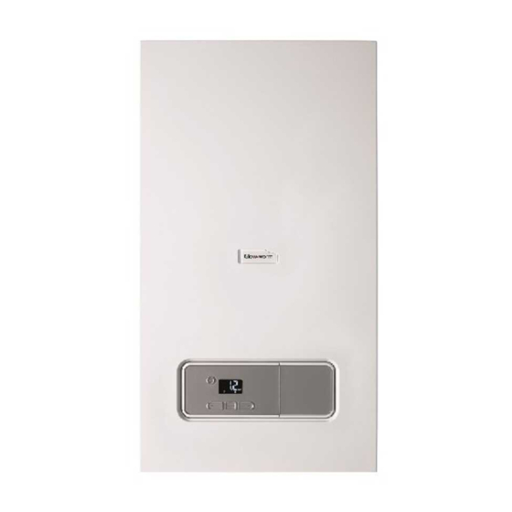
Glow-worm Energy7 Series Operating Instructions Manual
Hide thumbs
Also See for Energy7 Series:
- Operating instructions manual (16 pages) ,
- Installation and maintenance instructions manual (60 pages)
Summary of Contents for Glow-worm Energy7 Series
- Page 1 Operating instruc- tions Energy 12r ‑A (H‑GB) Energy 15r ‑A (H‑GB) Energy 18r ‑A (H‑GB) Energy 25r ‑A (H‑GB) Energy 30r ‑A (H‑GB) Energy GB, IE...
-
Page 2: Table Of Contents
Contents Contents Decommissioning...... 12 Temporarily decommissioning Safety ..........3 the product........12 Action-related warnings ....3 Permanently decommissioning the product........13 Intended use ........3 Recycling and disposal..... 13 General safety information..... 4 Guarantee and customer Notes on the documentation ..7 service ........ -
Page 3: Safety
Safety 1 1 Safety ing installations and for do- mestic hot water generation. 1.1 Action-related warnings Intended use includes the fol- Classification of action-re- lowing: lated warnings – observance of the operating The action-related warnings instructions included for the are classified in accordance product and any other install- with the severity of the pos- ation components... -
Page 4: General Safety Information
1 Safety ▶ Do not use any electrical 1.3 General safety information switches, mains plugs, door- bells, telephones or other 1.3.1 Installation by skilled communication systems in tradesmen only the building. The installation, inspection, ▶ If it is safe to do so, close the maintenance and repair of the emergency control valve or product, as well as the gas ratio... - Page 5 Safety 1 – to the entire condensate 1.3.5 Risk of death due to explosive and flammable discharge system – to the expansion relief valve materials – to the drain pipework ▶ Do not use the product in – to constructional condi- storage rooms that contain tions that may affect the explosive or flammable sub-...
- Page 6 1 Safety ▶ Ensure that no chemical sub- stances are stored at the in- stallation site. 1.3.10 Cabinet-type casing Enclosing the product in cab- inet-type casing requires com- pliance with the applicable design instructions. ▶ Do not fit the casing on the product yourself.
-
Page 7: Notes On The Documentation
▶ You must observe all operating instruc- tions enclosed with the system compon- ents. Glow-worm is a licensed member of the Benchmark Scheme which aims to im- 2.2 Storing documents prove the standards of installation and ▶ Keep this manual and all other applic- commissioning of domestic heating and able documents safe for future use. -
Page 8: Information On The Data Plate
3 Product description 3.3 Information on the data plate Information Meaning on the data The data plate is mounted on the under- plate side of the product at the factory. Nominal heat output range The data plate keeps record of the country in domestic hot water mode in which the product is to be installed. -
Page 9: Operating Levels
Operation 4 3.5.1 Description of the display Button Meaning – Setting the domestic hot water temperature – Setting the heating flow tem- perature – Increase or decrease the selec- ted set value – Increase the display contrast – Activate the product: On/off (standby) –... -
Page 10: Basic Display
4 Operation 4.1.2 Switching on the product 2. Fill the heating installation. (→ Page 10) ▶ Switch on the product via the main 4.4 Filling the heating installation switch installed on-site. Caution. 4.2 Basic display Risk of material damage due to heating water that is ex- tremely calciferous or corros- ive or contaminated by chem-... -
Page 11: Setting The Operating Mode
Operation 4 4.5 Setting the operating mode Note The competent person may Note have adjusted the maximum Each time the product is switched possible temperature. on, the last selected operating mode is assumed. Condition: Temperature controlled by the control, with heating mode activated ▶... -
Page 12: Switching The Product To Standby Mode
5 Troubleshooting 6 Care and maintenance 4.9 Switching the product to standby mode 6.1 Maintenance ▶ Press the button for less than three An annual inspection of the product carried seconds. out by a competent person is a prerequis- ◁ Once the requirement currently in ite for ensuring that the product is perman- use has finished, the display will... -
Page 13: Permanently Decommissioning The Product
Have a competent person permanently dress that is provided on the back page, or decommission the product. you can visit www.glow-worm.co.uk. 8 Recycling and disposal ▶ The competent person who installed your product is responsible for the dis- posal of the packaging. -
Page 14: Appendix
Appendix Appendix A Adjustable values – overview Adjustable values Values Unit Increment, select Default set- ting Min. Max. Heating mode ℃ Heating flow temperature Current value Preset in the system DHW mode ℃ Hot water temperature Current value B Troubleshooting Fault Cause Measure... - Page 16 Vaillant Group UK LTD Nottingham Road ‒ Belper ‒ Derbyshire DE56 1JQ Telephone 01773 824639 ‒ Technical helpline 0330 100 7679 After sales service 0330 100 3142 www.glow-worm.co.uk 0020300880_00 0020300880_00 ‒ 02.03.2020 © These instructions, or parts thereof, are protected by copyright and may be reproduced or distributed only with the manufacturer's written consent.


Need help?
Do you have a question about the Energy7 Series and is the answer not in the manual?
Questions and answers