Table of Contents
Advertisement
Quick Links
© Copyright 2009
EVERTZ MICROSYSTEMS LTD.
5288 John Lucas Drive,
Burlington, Ontario, Canada
L7L 5Z9
Phone:
Sales Fax:
Tech Support Phone:
Tech Support Fax:
Revision 1.0 May 2009
The material contained in this manual consists of information that is the property of Evertz Microsystems and is intended solely for
the use of purchasers of the 2400 series products. Evertz Microsystems expressly prohibits the use of this manual for any
purpose other than the operation of the Routers.
All rights reserved. No part of this publication may be reproduced without the express written permission of Evertz Microsystems
Ltd. Copies of this guide can be ordered from your Evertz products dealer or from Evertz Microsystems.
Integrated Outdoor RF Fiber Transport System
Instruction Manual
+1 905-335-3700
+1 905-335-3573
+1 905-335-7570
+1 905-335-7571
2400ODU
Internet:
Sales:
Tech Support: service@evertz.com
Web Page:
sales@evertz.com
http://www.evertz.com
Advertisement
Table of Contents

Subscribe to Our Youtube Channel
Related Manuals for evertz 2400ODU


Summary of Contents for evertz 2400ODU
- Page 1 Revision 1.0 May 2009 The material contained in this manual consists of information that is the property of Evertz Microsystems and is intended solely for the use of purchasers of the 2400 series products. Evertz Microsystems expressly prohibits the use of this manual for any purpose other than the operation of the Routers.
- Page 2 This page left intentionally blank...
- Page 3 IMPORTANT SAFETY INSTRUCTIONS The lightning flash with arrowhead symbol within an equilateral triangle is intended to alert the user to the presence of un-insulated “Dangerous voltage” within the product’s enclosure that may be of sufficient magnitude to constitute a risk of electric shock to persons. The exclamation point within an equilateral triangle is intended to alert the user to the presence of important operating and maintenance (Servicing) instructions in the literature accompanying the product.
- Page 4 WARNING Changes or modifications not expressly approved by Evertz Microsystems Ltd. could void the user’s authority to operate the equipment. Use of unshielded plugs or cables may cause radiation interference. Properly shielded interface cables with the shield connected to the chassis ground of the device must be used.
- Page 5 Evertz products are for informational use only and are not warranties of future performance, either expressed or implied. The only warranty offered by Evertz in relation to this product is the Evertz standard limited warranty, stated in the sales contract or order confirmation form.
- Page 6 2400ODU Integrated Outdoor RF Fiber Transport System CAUTION If the LNB POWER LED is on or flashing on any of the 2408LT’s, there will be DC voltage for LNB power at the associated RF 1-4 connector on the bottom of the unit.
-
Page 7: Table Of Contents
2400ODU Integrated Outdoor RF Fiber Transport System TABLE OF CONTENTS OVERVIEW............................1 INSTALLATION........................... 4 2.1. MOUNTING..........................4 2.2. RF CONNECTIONS........................5 2.3. AC INPUT CONNECTIONS AND GROUNDING................ 6 2.3.1. AC INPUT (without +IEC option)..................7 2.3.2. AC INPUT (with +IEC option)..................7 2.3.3. - Page 8 2400ODU Integrated Outdoor RF Fiber Transport System Figures Figure 1-1: 2400ODU, Front Door Closed ..................... 2 Figure 1-2: 2400ODU, Front Door Open, Swing Panel with 2408LT's Mounted ........2 Figure 1-3: 2400ODU, Swing Panel Open, Inner Panel with 2400PSU-8 Mounted ..........................3 Figure 2-1: 2400ODU Mounting and Dimensional Information..............
-
Page 9: Overview
2400ODU Integrated Outdoor RF Fiber Transport System OVERVIEW The 2400ODU provides a convenient, pre-integrated package for fiber transport of Satellite, OTA DTV and other signals within the extended L-Band range and below. Contained in a compact, weatherproof enclosure are up to four 2408LT fiber optic transmitters and a 2400PSU-8 power supply. -
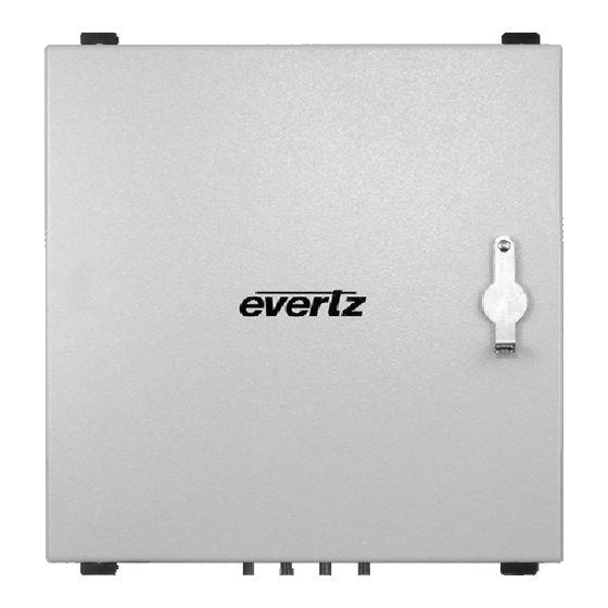
Page 10: Figure 1-1: 2400Odu, Front Door Closed
2400ODU Integrated Outdoor RF Fiber Transport System Figure 1-1: 2400ODU, Front Door Closed Figure 1-2: 2400ODU, Front Door Open, Swing Panel with 2408LT's Mounted Page - 2 Revision 1.0... -
Page 11: Figure 1-3: 2400Odu, Swing Panel Open, Inner Panel With 2400Psu-8 Mounted
2400ODU Integrated Outdoor RF Fiber Transport System Figure 1-3: 2400ODU, Swing Panel Open, Inner Panel with 2400PSU-8 Mounted Page - 3 Revision 1.0... -
Page 12: Installation
The 2400ODU comes with mounting brackets pre-installed. Be sure to choose appropriate fasteners suitable for the surface/material on which the 2400ODU is to be mounted. Also ensure that the fasteners are strong enough to support the 2400ODU’s weight. The mounting hole locations and dimensional information of the 2400ODU are illustrated in Figure 1-1: 9.2"... -
Page 13: Rf Connections
2400ODU Integrated Outdoor RF Fiber Transport System When choosing a mounting location, it is recommended that the 2400ODU be positioned such that it is out of direct sunlight for the duration of the day. Solar heat gain caused by direct sunlight can significantly raise the interior temperatures of the 2400ODU over the temperature rise incurred by ambient air temperatures alone. -
Page 14: Ac Input Connections And Grounding
As standard, the 2400ODU is equipped, from the factory, with a NEMA5-15R duplex receptacle and junction box. When the 2400ODU is equipped with the +IEC option, the unit is intended for applications outside of North America. When equipped with this option, the 2400PSU-8 is included with a pair of male IEC320 power inlets and the NEMA5-15R receptacle is not installed. -
Page 15: Ac Input (Without +Iec Option)
In this case, the incoming power feeds(s) to the 2400ODU should be terminated with IEC320 female connector(s). If a single power feed is to be provided to the 2400ODU, a two-position power strip should be used to provide a dual power connection to a single source. Wiring should be protected by appropriately sized upstream circuit breaker(s). -
Page 16: Fiber Connections
2.4. FIBER CONNECTIONS On the bottom of the 2400ODU, a ¾” (19mm) hole is provided for landing conduit for fiber optic cable. From the factory, a watertight plug is installed in the hole, which may be removed for cable installation. -
Page 17: Care And Handling Of Optical Fiber
2408LT units 1 and 3. Figure 2-8 illustrates fiber cable routing and connection to the 2408LT’s. Figure 2-8: 2400ODU Swing Panel Fiber Cable Routing 2.5. -
Page 18: Assembly
2400ODU Integrated Outdoor RF Fiber Transport System 2.5.2. Assembly Assembly or repair of the laser sub-module is done only at Evertz facility and performed only by Evertz technical personnel. 2.5.3. Labeling Certification and Identification labels are combined into one label. -
Page 19: Operation And Maintenanace
3.1. LIGHTNING SUPRESSORS The lightning supressors are located inside the 2400ODU, directly opposite and integral to the external RF connections. These supressors contain gas tubes that may be replaced after a lightning strike or other surge. The gas tube itself is located behind the threaded access cover. -
Page 20: Replacement And Addition Of Modules
Installation of the replacement module is the reverse process of above. If a 2400ODU model was purchased without being fully populated with 2408LT fiber transmitters (max four pieces per 2400ODU), additional transmitters may be easily added at any time. Expansion kits are available from Evertz which contain the fiber transmitter and the required cabling and hardware for installation. -
Page 21: 00Odu Specifications
2400ODU Integrated Outdoor RF Fiber Transport System 2400ODU SPECIFICATIONS 4.1. RF INPUT Number of Inputs: 1-4 depending on number of installed fiber transmitters Connector: F-Type (N-type optional) Impedance75Ω (50Ω optional): Frequency Range120 to 2250MHz Input Power Range: -10dBm to -60dBm LNB Voltage: 18V DC, 13.5V DC, off (selectable) -
Page 22: Physical
2400ODU Integrated Outdoor RF Fiber Transport System 4.5. PHYSICAL Dimensions Without Flanges: 9" D x 16" W x 16" H (229mm D x 407mm W x 407mm H) Knockouts: 2x¾" (19mm) Finish: Textured light grey (RAL 7035) powder coat Environmental Temperature: -20 to +55°C ambient air temperature...
Need help?
Do you have a question about the 2400ODU and is the answer not in the manual?
Questions and answers